|
Open CASCADE Technology 8.0.0
|

|
|
Open CASCADE Technology 8.0.0
|
|
OCCT provides a strong set of built-in Interactive Objects for rapid application development, but the real power and flexibility of Application Interactive Services (AIS) could be revealed by subclassing and implementing custom presentations. In this tutorial we will focus on the development of a custom AIS_InteractiveObject and show the basics step by step.
Let's start from the very beginning and try subclassing AIS_InteractiveObject object:
DEFINE_STANDARD_RTTI_INLINE() macro will register the new class within the OCCT Run-Time Type Information (RTTI) system. This step is optional (you may skip it if you are not going to use methods like Standard_Transient::DynamicType() in application code), but it is a common practice while subclassing OCCT classes.
The AIS_InteractiveObject interface defines only a couple of pure virtual methods - ::Compute() defining an object presentation and ::ComputeSelection() defining a selectable (pickable) volume. Selection and presentation are two independent mechanisms in AIS. Presentation rendering is done with help of OpenGL or a similar low-level graphics library, while selection doesn't depend on a graphic driver at all. Providing an empty implementation of these two methods would be enough for adding the object to AIS_InteractiveContext (::Display()), but obviously nothing will appear on the screen.
To go ahead, we need to define some presentation of our object. OCCT provides a set of presentation building tools for common elements like arrows, shapes, boxes, etc. These tools could be found within Prs3d, StdPrs and DsgPrs packages:
TopoDS_Shape).
Presentation builders are reusable bricks for constructing AIS objects. Standard OCCT interactive objects highly rely on them, so that you may easily replicate AIS_Shape presentation for displaying a shape with just a couple of lines calling StdPrs_ShadedShape:

StdPrs_ShadedShape presentation builder.PrsMgr_PresentableObject::Compute() method takes three arguments:
PrsMgr_PresentationManager). Rarely used parameter, but might be necessary for some advanced use cases.Prs3d_Presentation or Graphic3d_Structure). Defines the structure to fill in with presentation elements.AIS_InteractiveObject::SetDisplayMode() or by AIS_InteractiveContext::Display().For each supported display mode, the Presentation Manager creates a dedicated Prs3d_Presentation and stores it within the object itself as a list of presentations PrsMgr_PresentableObject::Presentations(). It is a good practice to reject unsupported display modes within ::Compute() method:
This wouldn't, however, prevent application from displaying the object with another display mode like this:
The code above will display MyAisObject with display mode equal to 100, and after ::Compute() modifications nothing will be displayed on the screen. AIS will still create a presentation with specified display mode, but it will be empty - method ::AcceptDisplayMode() could be overridden to disallow even creation of an empty presentation:
AIS_InteractiveContext::Display() checks if requested display mode is actually supported by the object, and uses default display mode (0) if it is not. StdPrs_ShadedShape prepares a shaded (triangulated) presentation of a shape, while StdPrs_WFShape creates a wireframe presentation with B-Rep wire boundaries:

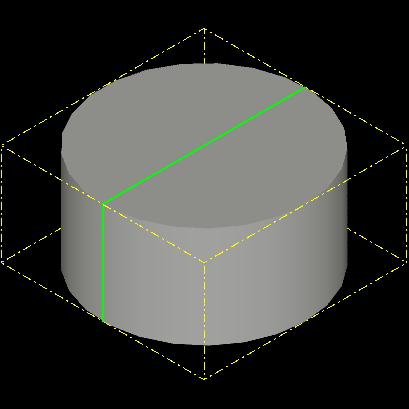
StdPrs_ShadedShape + StdPrs_WFShape presentation builders.Presentation builders take the Prs3d_Drawer object defining various attributes - material of shaded shape, number of isolines in wireframe mode, tessellation quality, line colors and many others. PrsMgr_PresentableObject defines myDrawer property with default attributes. StdPrs makes it easy to display topological shapes. With the help of Prs3d tools we may display elements like arrows, boxes or text labels. Let's extend our presentation with a second display mode 1 showing a bounding box using Prs3d_BndBox builder:
Now, displaying an object with display mode 1 will show a box:

Prs3d_BndBox presentation builder.AIS disallows activating multiple display modes at the same time, so that these presentation modes should be alternatives to each other. But AIS may use non-active display mode for highlighting purposes - like wireframe (AIS_Wireframe) presentation displayed on top of shaded (AIS_Shaded) presentation for selected AIS_Shape objects.
Let's define a dedicated enumeration for display modes supported by our interactive object and setup the 1st (MyDispMode_Highlight) display mode for highlighting with help of PrsMgr_PresentableObject::SetHilightMode():

In this particular use case we've used the method AIS_InteractiveContext::HilightWithColor() instead of ::SetSelected() - just because our object is not selectable yet and ::SetSelected() wouldn't work. Highlighted presentation appears on the screen with modulated color (see left screenshot above). Using a dedicated display mode for highlighting (right screenshot above) allows customizing presentation in selected / highlighted states.
Prs3d_Presentation might be filled in by the following primitives:
This triplet of primitives is what graphics hardware is capable of rendering, so that it could be transferred directly to low-level graphics libraries in the form of Vertex Buffer Objects (VBO). Each primitive array consists of an array of vertex attributes (position, normal, texture coordinates, vertex colors, etc.) and optional array of indices. The latter one avoids duplicating vertices shared between connected elements (triangles, polylines) in attributes array.
Graphic3d_ArrayOfPrimitives and it's subclasses provide a convenient interface for filling in primitive arrays:
Graphic3d_ArrayOfPrimitives::AddVertex() appends a vertex with specified attributes to the end of the array (within the range specified at construction time).Graphic3d_ArrayOfPrimitives::AddEdges() appends indices, starting with 1. Each line segment is defined by two consequential edges, each triangle is defined by three consequential edges.Let's extend our sample and display a cylinder section contour defined by array of indexed segments (e.g. a polyline of four vertices):
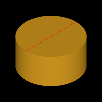
Graphic3d_ArrayOfSegments.The process is quite straightforward:
Graphic3d_Group using Prs3d_Presentation::NewGroup();Graphic3d_Group::SetGroupPrimitivesAspect();Graphic3d_Group::AddPrimitiveArray().Standard presentation builders like StdPrs_ShadedShape / StdPrs_WFShape internally do exactly the same thing - a tessellated representation of a shape is added to presentation in form of triangles (shaded), line segments (wireframe and free edges) and markers (free shape vertices).
A single Graphic3d_Group normally defines just a single primitive array, but it is technically possible adding more arrays to the same group Graphic3d_Group::AddPrimitiveArray() and with different aspects Graphic3d_Group::SetPrimitivesAspect(), which might be considered in advanced scenarios.
Method Graphic3d_Group::AddText() allows adding text labels to a presentation. Internally, text labels are rendered as an array of textured triangles using texture atlas created from a font, but this complex logic is hidden from the user.
Graphic3d_Aspects is a class defining display properties of a primitive array (Graphic3d_Group::SetGroupPrimitivesAspect()) - material, shading model, color, texture maps, blending mode, line width and others.
There are also subclasses Graphic3d_AspectFillArea3d (triangles), Graphic3d_AspectLine3d (lines), Graphic3d_AspectMarker3d (markers) and Graphic3d_AspectText3d (text labels) defined as specializations for a specific primitive array type. These subclasses exist for historical reasons and are treated by renderers in exactly the same way.
It is technically possible to create transient aspects directly within ::Compute() method like this:
While this code would work as expected, but prevents further dynamic updates of presentation aspects without recomputing entire presentation. Instead, it is preferred taking attributes from PrsMgr_PresentableObject::myDrawer / ::Attributes() or storing custom attributes as class fields. Prs3d_Drawer defines a set of attributes used by AIS presentation builders, but the same parameters might be used by a custom builder as well.
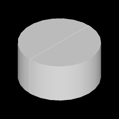
It is also preferred preallocating attributes in the class constructor. This would allow changing attributes without recomputing the entire presentation - just by calling PrsMgr_PresentableObject::SynchronizeAspects() after modifications. Our custom object uses myDrawer->ShadingAspect() and myDrawer->WireAspect() aspects, so let's initialize them explicitly - assign silver material for shading and green color to line segments:
Previously, we've used StdPrs_ShadedShape for displaying cylinder geometry. The Prs3d package provides a simpler way for displaying geometry like cylinders, spheres and toruses - based on the Prs3d_ToolQuadric interface. This interface allows bypassing creation of a complex B-Rep (TopoDS_Shape) definition of a simple geometry, and to avoid using general-purpose tessellators like BRepMesh.
This difference could be negligible for a small number of such objects, but might become considerable for larger amounts. The B-Rep definition of a valid cylinder includes 2 unique
TopoDS_Vertex, 3TopoDS_Edge, 3TopoDS_Wire, 3TopoDS_Face, 1TopoDS_Shelland 1TopoDS_Solid. Internally eachTopoDS_Edgealso defines curves (Geom_Curveas well as 2D parametricGeom2d_Curve) and eachTopoDS_Facedefines analytical surface (Geom_Surface). Meshing such geometry with the help ofBRepMeshis much more complicated than one may think. A plenty of data structures (memory!) and computations (time!) for displaying a geometry that could be triangulated by a simple for loop.
Prs3d_ToolQuadric solves this problem by creating a triangulation for such kinds of shapes in a straight-forward way. Let's try using Prs3d_ToolCylinder in our sample:

Prs3d_ToolCylinder (10 slices).Well... that looks a little bit edgy. Quadric builder creates a triangulation taking the following parameters:
gp_Trsf to apply (original geometry is defined within some reference coordinate system).Let's increase number of subdivisions from 10 to 25:

Prs3d_ToolCylinder (25 slices).It looks much better now! Note that Prs3d_ToolCylinder could be used for building both cones and cylinders depending on top/bottom radius definition.
There is one issue though - our cylinder doesn't have top and bottom anymore! To fix this problem we will use one more quadric builder Prs3d_ToolDisk:
Now our cylinder looks solid! The sample above merges two triangulations into a single one instead of appending each primitive array individually.
This looks like a minor difference, but it might have a dramatic impact on performance in case of a large scene, as each Graphic3d_ArrayOfPrimitives is mapped into a dedicated draw call at graphic driver (OpenGL) level.

Prs3d_ToolCylinder + Prs3d_ToolDisk.As an exercise, let's try computing a triangulation for cylinder disk without help of Prs3d_ToolDisk builder:

The disk is here, but it has a strange color - like it is not affected by lighting. This happens when vertex normals are defined incorrectly. In our case we defined disk normal as -DZ (see the second argument of Graphic3d_ArrayOfTriangles::AddVertex()), but normal direction should be also aligned to triangulation winding rule. Graphic driver defines the front side of triangle using clockwise order of triangle nodes, and normal should be defined for a front side of triangle - e.g. it should be gp::DZ() in our case. After reversing vertex normal direction, cylinder looks exactly like when Prs3d_ToolDisk was used.
Front / back face orientation might be displayed using different material based on Graphic3d_Aspects::SetDistinguish() flag and ::FrontMaterial() / ::BackMaterial() setup.
In the first part of the tutorial we have created a custom AIS object MyAisObject computing presentation by implementing the PrsMgr_PresentableObject::Compute() interface. In this part we will extend our object with interactive capabilities and make it selectable through implementing SelectMgr_SelectableObject interface.
Let's do the first step and put into ::ComputeSelection() method some logic. This method should fill in the SelectMgr_Selection argument with SelectMgr_SensitiveEntity entities defining selectable elements - triangulations, polylines, points and their composition. Select3D_SensitiveBox is probably the simplest way to define selectable volume - by it's bounding box:
SelectMgr_EntityOwner is a key object in selection logic - it serves as an identifier of a pickable object or it's part. You may see this object in methods like AIS_InteractiveContext::DetectedOwner(), Owners are stored within the list of selection objects AIS_Selection and it received by methods like AIS_InteractiveContext::SetSelected() and AIS_InteractiveContext::AddOrRemoveSelected(). From the Selector's point of view, AIS_InteractiveObject is just a drawer for SelectMgr_EntityOwner.
The 0th selection mode normally defines a single Owner of the entire object. To make a composite object selectable as whole, we add to Selection as many SensitiveEntity as necessary referring to the same Owner. It might look confusing from first glance, that SelectMgr_SensitiveEntity stores SelectMgr_EntityOwner as a class field, and not in the opposite way (SelectMgr_EntityOwner doesn't store the list of SelectMgr_SensitiveEntity defining it's picking volume).
For local selection (selection of object parts) we create individual Owners for each part and add SensitiveEntity to Selection in the same way. Owner may store an additional identifier as a class field, like StdSelect_BRepOwner stores TopoDS_Shape as an identifier of picked sub-shape with AIS_Shape object.
In a similar way as StdPrs_ShadedShape is a presentation builder for TopoDS_Shape, the StdSelect_BRepSelectionTool can be seen as a standard selection builder for shapes:
Internally, StdSelect_BRepSelectionTool iterates over sub-shapes and appends to the Selection (theSel) entities like Select3D_SensitiveTriangulation (for faces) and Select3D_SensitiveCurve (for edges).
Previously, we have used Prs3d_ToolCylinder to triangulate a cylinder, so let's try to construct Select3D_SensitivePrimitiveArray from the same triangulation:
Selection is computed independently from presentation, so that they don't have to match each other. But inconsistency between presentation and selection might confuse a user, when he will not be able to pick an object clearly displayed under the mouse cursor. These issues might happen, for example, when selection uses tessellated representation of the same geometry computed with different parameters (different number of subdivisions, or different deflection parameters).
As in case of ::Compute(), it makes sense defining some enumeration of selection modes supported by specific object and reject unsupported ones to avoid unexpected behavior:
Unlike display modes, AIS_InteractiveContext allows activating an arbitrary combination of selection modes. A user should be careful to activate only the modes that actually make sense and may work together.
Selection mode to activate could be specified while displaying the object (passing -1 instead of 0 would display an object with deactivated selection):
Later on AIS_InteractiveContext::SetSelectionModeActive(), or it's wrappers AIS_InteractiveContext::Activate() and AIS_InteractiveContext::Deactivate(), could be used to enable or disable desired selection modes one by one.
As has been mentioned in the previous section, SelectMgr_EntityOwner is a key object which can be used as an identifier of selectable part(s). Naturally, you might want to subclass it to put some application-specific ids for identification of selected parts. But there are more things you may do with the Owner class like customized highlighting.
Let's start from the beginning and define a custom Owner class:
SelectMgr_EntityOwner doesn't define any pure virtual methods, and can be instanced straight ahead, like it was done within MyAisObject::ComputeSelection() implementation above. Let's revert usage of a dedicated display mode for highlighting (remove SetHilightMode() in MyAisObject constructor) and use our new class MyAisOwner within ::ComputeSelection():
The further logic creating sensitive entities and filling in Selection could be left as is. Substitution of SelectMgr_EntityOwner with MyAisOwner currently doesn't change behavior and we see highlighting of the entire object through color modulation. This is because default implementation of SelectMgr_EntityOwner for highlighting logic looks like this (simplified):
SelectMgr_EntityOwner::HilightWithColor().Now, let's override the SelectMgr_EntityOwner::HilightWithColor() method and display a bounding box presentation:
SelectMgr_EntityOwner::HilightWithColor() doesn't receive a presentation to fill in as an argument; highlight presentation should be manually created and even explicitly displayed on the screen. To avoid code duplication, the code above reuses MyAisObject::Compute() already implementing computation of highlight presentation.
MyAisOwner::HilightWithColor().The visual result of the selected object looks exactly the same as when we've used a dedicated highlight mode. One thing became broken, though - highlighting remains displayed even after clearing selection. To fix this issue, we need implementing SelectMgr_EntityOwner::Unhilight() and hide our custom presentation explicitly:
Another problem is that the object is no longer dynamically highlighted. To fix that we need to handle PrsMgr_PresentationManager::IsImmediateModeOn() specifically. Within this mode turned ON, presentation should be displayed on the screen with help of PrsMgr_PresentationManager::AddToImmediateList() method (it will be cleared from the screen automatically on the next mouse movement):
We may create two dedicated presentations for dynamic highlighting or reuse existing one for both cases with help of a transient object Prs3d_PresentationShadow.
Let's go further and make dynamic highlighting a little bit more interesting - by drawing a surface normal at the point where mouse picked the object:
Code above does not store our new highlight presentation as a property of MyAisOwner, and instead uses SelectMgr_SelectableObject::GetHilightPresentation() method to create a presentation stored directly inside of our interactive object.
Next trick is passing through the last picking results in StdSelect_ViewerSelector. Dynamic highlighting is expected to be called right after picking, so that highlighted Owner should be always found in picking results. StdSelect_ViewerSelector::Picked() returns entities in the descending order of their distance from picking ray origin (mouse cursor); normally our Owner should be the very first one in this list when no selection filters are assigned to AIS_InteractiveContext.
SelectMgr_SortCriterion provides us useful information like 3D point on detected object lying on the picking ray, and surface normal direction at this point (actually, it would be a normal to a picked triangle), which we display as an arrow with help of Prs3d_Arrow presentation builder.
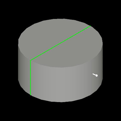
Result looks pretty nice on the screenshot, but has interaction problems - once displayed, an arrow is no longer updated with further mouse movements. But this behavior is not a bug - AIS calls MyAisOwner::HilightWithColor() only when picking Owner changes to avoid unnecessary Viewer updates. To override this behavior, we may override SelectMgr_EntityOwner::IsForcedHilight() option:
This solves the problem within our specific use case. Keep in mind that most objects don't need updating highlight presentation on every mouse move; overriding this flag everywhere would be a waste of resources and may cause performance issues - use it sparingly.
AIS provides one more alternative to handle presentation highlighting, which is managed by option SelectMgr_SelectableObject::IsAutoHilight(). By default, this option is turned ON and redirects highlighting logic to SelectMgr_EntityOwner::HilightWithColor() demonstrated in the previous section. Turning this option OFF redirects highlighting logic to the interactive object itself SelectMgr_SelectableObject::HilightSelected().
Apart from moving the logic from Owner to Interactive Object, this approach allows handling highlighting of all selected Owners within the same Object at once and sharing a common presentation instead of per-Owner presentation - improving performance and reducing memory utilization in case of a large number of small selectable elements, like mesh nodes in MeshVS_Mesh object.
The further optimization of such a scenario would be using a single Owner for the entire Object storing the list of selected elements within the Owner itself - as utilized by AIS_PointCloud object for highlighting individual points.
We wouldn't describe these advanced techniques here in detail - let's just summarize main highlighting approaches available in AIS:
PrsMgr_PresentableObject::Compute() and displayed with color modulation by AIS logic.AIS_TextLabel.PrsMgr_PresentableObject::Compute() and displayed with color modulation by AIS logic.AIS_Shape, displayed in AIS_Shaded display mode and highlighted using AIS_Wireframe display mode (default behavior). See also PrsMgr_PresentableObject::SetHilightMode().SelectMgr_EntityOwner and managed by SelectMgr_EntityOwner::HilightWithColor().StdSelect_BRepOwner for selection of sub-shapes.SelectMgr_SelectableObject::GetHilightPresentation() / ::GetSelectPresentation() methods).SelectMgr_EntityOwner::HilightWithColor() with SelectMgr_SelectableObject::IsAutoHilight() turned ON.AIS_PointCloud.SelectMgr_SelectableObject::HilightSelected() with SelectMgr_SelectableObject::IsAutoHilight() turned OFF.MeshVS_Mesh.PrsMgr_PresentableObject::Compute() and manually updated (recomputed or modified aspects) on highlight events.AIS_Manipulator.The number of options looks overwhelming but in general, it is better to stick to the simplest approach working for you and consider alternatives only when you have to.
Dynamic highlighting is only one of scenarios where SelectMgr_EntityOwner could be useful. Another feature is an interface for handling a mouse click SelectMgr_EntityOwner ::HandleMouseClick().
This interface is useful for defining some user interface elements like buttons, and most likely your application will use a more comprehensive GUI framework for this purpose instead of AIS. But let's have some fun and make our object to change a color on each mouse click:
Looks pretty simple. Now let's make things more interesting and launch some simple object animation on each click. We use a couple of global (static) variables in our sample for simplicity - don't do that in a real production code.
Animation is a complex topic that is worth a dedicated article - let's not go too deep in detail here. To perform animation in a non-interrupted way, it should be handled by some class like AIS_ViewController, which is responsible for managing user input events and for 3D viewer updates. To utilize it, you need adding a custom object animation to AIS_ViewController::ObjectsAnimation() or adding custom view animation to AIS_ViewController::ViewAnimation(). Somewhere in application this might look like this:
The final sample could be seen by calling QATutorialAisObject command from Draw Harness plugin QAcommands (TKQADraw toolkit):
You may also take a look onto source code of this command at src/Draw/TKQADraw/QADraw/QADraw_Tutorials.cxx if you have some problems following the tutorial.