|
Open CASCADE Technology
6.8.0
|
|
|
Open CASCADE Technology
6.8.0
|
|
Modeling Data supplies data structures to represent 2D and 3D geometric models. This manual explains how to use Modeling Data. For advanced information on modeling data, see our offerings on our web site at www.opencascade.org/support/training/
Geometry Utilities provide the following services:
In modeling, it is often required to approximate or interpolate points into curves and surfaces. In interpolation, the process is complete when the curve or surface passes through all the points; in approximation, when it is as close to these points as possible. This component provides both high and low level services to approximate or interpolate points into curves and surfaces. The lower level services allow performing parallel approximation of groups of points into groups of Bezier or B-spline curves.
The class PEquation from GProp package allows analyzng a collection or cloud of points and verifying if they are coincident, collinear or coplanar within a given precision. If they are, the algorithm computes the mean point, the mean line or the mean plane of the points. If they are not, the algorithm computes the minimal box, which includes all the points.
Packages Geom2dAPI and GeomAPI provide simple methods for approximation and interpolation with minimal programming
The class Interpolate from Geom2dAPI package allows building a constrained 2D BSpline curve, defined by a table of points through which the curve passes. If required, the parameter values and vectors of the tangents can be given for each point in the table.
The class Interpolate from GeomAPI package allows building a constrained 3D BSpline curve, defined by a table of points through which the curve passes. If required, the parameter values and vectors of the tangents can be given for each point in the table.
From this object, the BSpline curve may be requested as follows:
The class PointsToBSpline from Geom2dAPI package allows building a 2DBSpline curve, which approximates a set of points. You have to define the lowest and highest degree of the curve, its continuity and a tolerance value for it.The tolerance value is used to check that points are not too close to each other, or tangential vectors not too small. The resulting BSpline curve will beC2 or second degree continuous, except where a tangency constraint is defined on a point through which the curve passes. In this case, it will be only C1continuous.
The class PointsToBSpline from GeomAPI package allows building a 3D BSplinecurve, which approximates a set of points. It is necessary to define the lowest and highest degree of the curve, its continuity and tolerance. The tolerance value is used to check that points are not too close to each other,or that tangential vectors are not too small.
The resulting BSpline curve will be C2 or second degree continuous, except where a tangency constraint is defined on a point, through which the curve passes. In this case, it will be only C1 continuous. This class is instantiated as follows:
From this object, the BSpline curve may be requested as follows:
The class PointsToBSplineSurface from GeomAPI package allows building a BSpline surface, which approximates or interpolates a set of points.
Packages AppDef and AppParCurves provide low-level functions, allowing more control over the approximations.
AppDef package provides low-level tools to allow parallel approximation of groups of points into Bezier or B-Spline curves using multiple point constraints.
The following low level services are provided:
Definition of an array of point constraints:
The class MultiLine allows defining a given number of multipoint constraints in order to build the multi-line, multiple lines passing through ordered multiple point constraints.
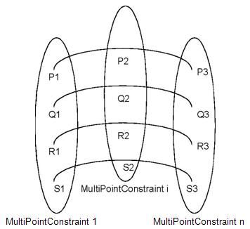
Definition of a set of point constraints:
The class MultiPointConstraint allows defining a multiple point constraint and computing the approximation of sets of points to several curves.
Computation of an approximation of a Bezier curve from a set of points:
The class Compute allows making an approximation of a set of points to a Bezier curve
The class BSplineCompute allows making an approximation of a set of points to a BSpline curve.
The class TheVariational allows fairing the approximation curve to a given number of points using a least squares method in conjunction with a variational criterion, usually the weights at each constraint point.
AppParCurves package provides low-level tools to allow parallel approximation of groups of points into Bezier or B-Spline curve with parametric or geometric constraints, such as a requirement for the curve to pass through given points, or to have a given tangency or curvature at a particular point.
The algorithms used include:
The following low-level services are provided:
The class ConstraintCouple allows you associating an index to an object to compute faired curves using AppDef_TheVariational.
The class MultiCurve allows defining the approximation of a multi-line made up of multiple Bezier curves.
The class MultiBSpCurve allows defining the approximation of a multi-line made up of multiple BSpline curves.
The class MultiPoint allows defining groups of 2D or 3D points making up a multi-line.
Direct Construction methods from gce, GC and GCE2d packages provide simplified algorithms to build elementary geometric entities such as lines, circles and curves. They complement the reference definitions provided by the gp, Geom and Geom2d packages.
For example, to construct a circle from a point and a radius using the gp package, it is necessary to construct axis Ax2d before creating the circle. If gce package is used, and Ox is taken for the axis, it is possible to create a circle directly from a point and a radius.
The following algorithms used to build entities from non-persistent gp entities are provided by gce package.
Each class from gp package, such as Circ, Circ2d, Mirror, Mirror2d, etc., has the corresponding MakeCirc, MakeCirc2d, MakeMirror, MakeMirror2d, etc. class from gce package.
It is possible to create a point using a gce package class, then question it to recover the corresponding gp object.
This is useful if you are uncertain as to whether the arguments can create the gp object without raising an exception. In the case above, if Point1 and Point2 are closer than the tolerance value required by MakeLin2d, the function Status will return the enumeration gce_ConfusedPoint. This tells you why the gp object cannot be created. If you know that the points Point1 and Point2 are separated by the value exceeding the tolerance value, then you may create the gp object directly, as follows:
GC and GCE2d packages provides an implementation of algorithms used to build entities from Geom and Geom2D packages. They implement the same algorithms as the gce package but create persistent entities, and also contain algorithms for trimmed surfaces and curves. The following algorithms are available:
Each class from GCE2d package, such as Circle, Ellipse, Mirror, etc., has the corresponding MakeCircle, MakeEllipse, MakeMirror, etc. class from Geom2d package. Besides, the class MakeArcOfCircle returns an object of type TrimmedCurve from Geom2d.
Each class from GC package, such as Circle, Ellipse, Mirror, etc., has the corresponding MakeCircle, MakeEllipse, MakeMirror, etc. class from Geom package. The following classes return objects of type TrimmedCurve from Geom:
The following algorithms to convert geometric curves or surfaces into their BSpline or Bezier equivalents are provided by GeomConvert, Geom2dConvert and Convert packages:
The following characteristic points exist on parameterized curves in 3d space:
GCPnts package provides algorithms to calculate such points:
Let us take an adapted curve C, i.e. an object which is an interface between the services provided by either a 2D curve from the package Geom2d (in case of an Adaptor_Curve2d curve) or a 3D curve from the package Geom (in case of an Adaptor_Curve curve), and the services required on the curve by the computation algorithm. The adapted curve is created in the following way:
2D case :
3D case :
The algorithm is then constructed with this object:
The classes to calculate the minimum distance between points, curves, and surfaces in 2d and 3d are provided by GeomAPI and Geom2dAPI packages.
These packages calculate the extrema of distance between:
The Geom2dAPI_ExtremaCurveCurve class allows calculation of all extrema between two 2D geometric curves. Extrema are the lengths of the segments orthogonal to two curves.
The GeomAPI_ExtremaCurveCurve class allows calculation of all extrema between two 3D geometric curves. Extrema are the lengths of the segments orthogonal to two curves.
The GeomAPI_ExtremaCurveSurface class allows calculation of all extrema between a 3D curve and a surface. Extrema are the lengths of the segments orthogonal to the curve and the surface.
The GeomAPI_ExtremaSurfaceSurface class allows calculation of all extrema between two surfaces. Extrema are the lengths of the segments orthogonal to two surfaces.
Geom2d package defines geometric objects in 2dspace. All geometric entities are STEP processed. The objects are non-persistent and are handled by reference. The following objects are available:
Before creating a geometric object, it is necessary to decide how the object is handled. The objects provided by Geom2d package are handled by reference rather than by value. Copying an instance copies the handle, not the object, so that a change to one instance is reflected in each occurrence of it. If a set of object instances is needed rather than a single object instance, TColGeom2d package can be used. This package provides standard and frequently used instantiations of one-dimensional arrays and sequences for curves from Geom2d package. All objects are available in two versions:
The Geom package defines geometric objects in 3d space and contains all basic geometric transformations, such as identity, rotation, translation, mirroring, scale transformations, combinations of transformations, etc. as well as special functions depending on the reference definition of the geometric object (e.g. addition of a control point on a B-Spline curve,modification of a curve, etc.). All geometrical entities are STEP processed. The following non-persistent and reference-handled objects are available:
If a set of object instances is needed rather than a single object instance, TColGeom package can be used. This package provides instantiations of one- and two-dimensional arrays and sequences for curves from Geom package. All objects are available in two versions:
Packages GeomLProp, Geom2dLProp provide algorithms calculating the local properties of curves and surfaces
A curve (for one parameter) has the following local properties:
A surface (for two parameters U and V) has the following local properties:
The following methods are available:
Note that the B-spline curve and surface are accepted but they are not cut into pieces of the desired continuity. It is the global continuity, which is seen.
Open CASCADE Technology Topology allows accessing and manipulating objects data without dealing with their 2D or 3D representations. Whereas OCCT Geometry provides a description of objects in terms of coordinates or parametric values, Topology describes data structures of objects in parametric space. These descriptions use location in and restriction of parts of this space.
To provide its descriptions, OCCT abstract topology offers the following services:
A local coordinate system can be viewed as either of the following:
TopLoc package distinguishes two notions:
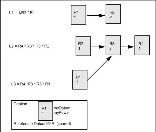
For example, consider three elementary coordinates: R1, R2, R3 The composite coordinates are: C1 = R1 * R2, C2 = R2 * R3 C3 = C1 * R3 C4 = R1 * C2
NOTE C3 and C4 are equal because they are both R1 * R2 * R3.
The TopLoc package is chiefly targeted at the topological data structure, but it can be used for other purposes.
TopLoc_Datum3D class represents a change of elementary coordinates. Such changes must be shared so this class inherits from MMgt_TShared. The coordinate is represented by a transformation gp_Trsfpackage. This transformation has no scaling factor.
The TopAbs package provides general enumerations describing the basic concepts of topology and methods to handle these enumerations. It contains no classes. This package has been separated from the rest of the topology because the notions it contains are sufficiently general to be used by all topological tools. This avoids redefinition of enumerations by remaining independent of modeling resources. The TopAbs package defines three notions:
TopAbs contains the TopAbs_ShapeEnum enumeration,which lists the different topological types:
A topological model can be considered as a graph of objects with adjacency relationships. When modeling a part in 2D or 3D space it must belong to one of the categories listed in the ShapeEnum enumeration. The TopAbspackage lists all the objects, which can be found in any model. It cannot be extended but a subset can be used. For example, the notion of solid is useless in 2D.
The terms of the enumeration appear in order from the most complex to the most simple, because objects can contain simpler objects in their description. For example, a face references its wires, edges, and vertices.
The notion of orientation is represented by the TopAbs_Orientation enumeration. Orientation is a generalized notion of the sense of direction found in various modelers. This is used when a shape limits a geometric domain; and is closely linked to the notion of boundary. The three cases are the following:
In each case the topological form used as the boundary of a geometric domain of a higher dimension defines two local regions of which one is arbitrarily considered as the default region.
For a curve limited by a vertex the default region is the set of points with parameters greater than the vertex. That is to say it is the part of the curve after the vertex following the natural direction along the curve.
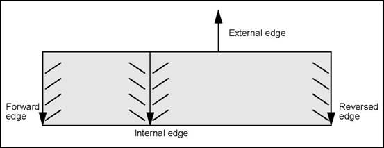
For a surface limited by an edge the default region is on the left of the edge following its natural direction. More precisely it is the region pointed to by the vector product of the normal vector to the surface and the vector tangent to the curve.
For a space limited by a face the default region is found on the negative side of the normal to the surface.
Based on this default region the orientation allows definition of the region to be kept, which is called the interior or material. There are four orientations defining the interior.
| Orientation | Description |
|---|---|
| FORWARD | The interior is the default region. |
| REVERSED | The interior is the region complementary to the default. |
| INTERNAL | The interior includes both regions. The boundary lies inside the material. For example a surface inside a solid. |
| EXTERNAL | The interior includes neither region. The boundary lies outside the material. For example an edge in a wire-frame model. |
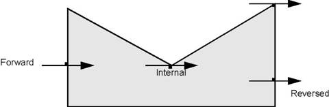
| Orientation | Association |
|---|---|
| FORWARD | Entering |
| REVERSED | Exiting |
| INTERNAL | Touching from inside |
| EXTERNAL | Touching from outside |
Along with the Orientation enumeration the TopAbs package defines four methods:
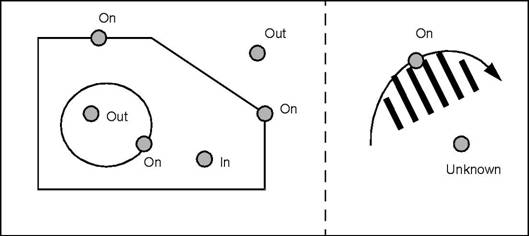
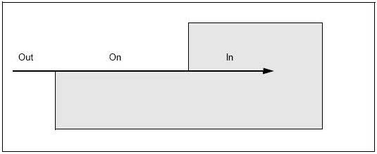
The TopAbs_State enumeration described the position of a vertex or a set of vertices with respect to a region. There are four terms:
| Position | Description |
|---|---|
| IN | The point is interior. |
| OUT | The point is exterior. |
| ON | The point is on the boundary(within tolerance). |
| UNKNOWN | The state of the point is indeterminate. |
The UNKNOWN term has been introduced because this enumeration is often used to express the result of a calculation, which can fail. This term can be used when it is impossible to know if a point is inside or outside, which is the case with an open wire or face.
The TopoDS package describes the topological data structure with the following characteristics:
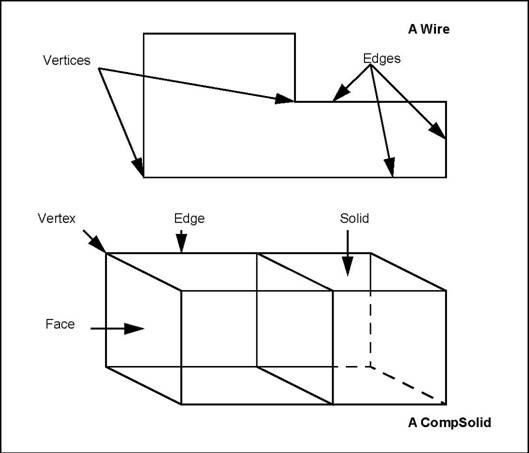
As stated above, OCCT Topology describes data structures of objects in parametric space. These descriptions use localization in and restriction of parts of this space. The types of shapes, which can be described in these terms, are the vertex, the face and the shape. The vertex is defined in terms of localization in parametric space, and the face and shape, in terms of restriction of this space.
OCCT topological descriptions also allow the simple shapes defined in these terms to be combined into sets. For example, a set of edges forms a wire; a set of faces forms a shell, and a set of solids forms a composite solid (CompSolid in Open CASCADE Technology). You can also combine shapes of either sort into compounds. Finally, you can give a shape an orientation and a location.
Listing shapes in order of complexity from vertex to composite solid leads us to the notion of the data structure as knowledge of how to break a shape down into a set of simpler shapes. This is in fact, the purpose of the TopoDS package.
The model of a shape is a shareable data structure because it can be used by other shapes. (An edge can be used by more than one face of a solid). A shareable data structure is handled by reference. When a simple reference is insufficient, two pieces of information are added - an orientation and a local coordinate reference.
The TopoDS_TShape class is the root of all shape descriptions. It contains a list of shapes. Classes inheriting TopoDS_TShape can carry the description of a geometric domain if necessary (for example, a geometric point associated with a TVertex). A TopoDS_TShape is a description of a shape in its definition frame of reference. This class is manipulated by reference.
The TopoDS_Shape class describes a reference to a shape. It contains a reference to an underlying abstract shape, an orientation,and a local reference coordinate. This class is manipulated by value and thus cannot be shared.
The class representing the underlying abstract shape is never referenced directly. The TopoDS_Shape class is always used to refer to it.
The information specific to each shape (the geometric support) is always added by inheritance to classes deriving from TopoDS_TShape. The following figures show the example of a shell formed from two faces connected by an edge.
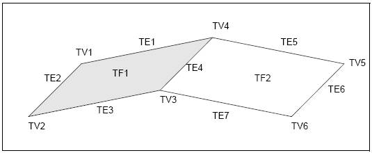
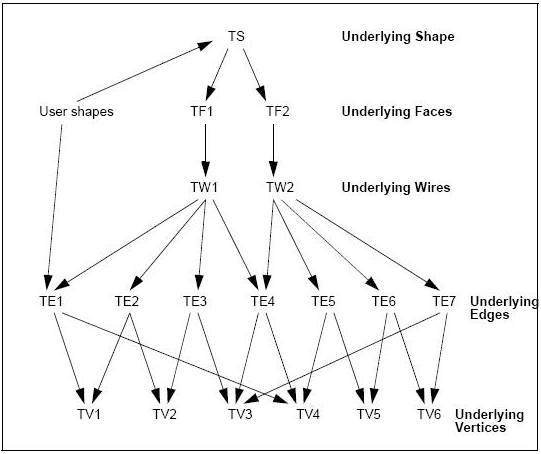
The wire TW1 references the edges from TE1 to TE4; TW2 references from TE4 to TE7.
The vertices are referenced by the edges as follows:TE1(TV1,TV4), TE2(TV1,TV2), TE3(TV2,TV3), TE4(TV3,TV4), TE5(TV4,TV5), TE6(T5,TV6),TE7(TV3,TV6).
Note that this data structure does not contain any back references. All references go from more complex underlying shapes to less complex ones. The techniques used to access the information are described later. The data structure is as compact as possible. Sub-objects can be shared among different objects.
Two very similar objects, perhaps two versions of the same object, might share identical sub-objects. The usage of local coordinates in the data structure allows the description of a repetitive sub-structure to be shared.
The compact data structure avoids the loss of information associated with copy operations which are usually used in creating a new version of an object or when applying a coordinate change.
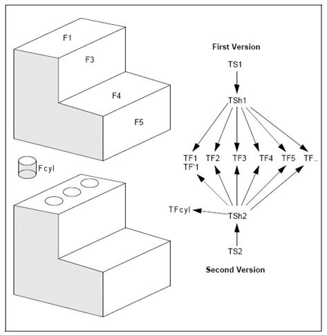
The following figure shows a data structure containing two versions of a solid. The second version presents a series of identical holes bored at different positions. The data structure is compact and yet keeps all information on the sub-elements.
The three references from TSh2 to the underlying face TFcyl have associated local coordinate systems, which correspond to the successive positions of the hole.
TopoDS is based on class TopoDS_Shape and the class defining its underlying shape. This has certain advantages, but the major drawback is that these classes are too general. Different shapes they could represent do not type them (Vertex, Edge, etc.) hence it is impossible to introduce checks to avoid incoherences such as inserting a face in an edge.
TopoDS package offers two sets of classes, one set inheriting the underlying shape with neither orientation nor location and the other inheriting TopoDS_Shape, which represent the standard topological shapes enumerated in TopAbs package.
The following classes inherit Shape : TopoDS_Vertex, TopoDS_Edge, TopoDS_Wire, TopoDS_Face, TopoDS_Shell, TopoDS_Solid,TopoDS_CompSolid, and TopoDS_Compound. In spite of the similarity of names with those inheriting from TopoDS_TShape there is a profound difference in the way they are used.
TopoDS_Shape class and the classes, which inherit from it, are the natural means to manipulate topological objects. TopoDS_TShape classes are hidden. TopoDS_TShape describes a class in its original local coordinate system without orientation. TopoDS_Shape is a reference to TopoDS_TShape with an orientation and a local reference.
TopoDS_TShape class is deferred; TopoDS_Shape class is not. Using TopoDS_Shape class allows manipulation of topological objects without knowing their type. It is a generic form. Purely topological algorithms often use the TopoDS_Shape class.
TopoDS_TShape class is manipulated by reference; TopoDS_Shape class by value. A TopoDS_Shape is nothing more than a reference enhanced with an orientation and a local coordinate. The sharing of TopoDS_Shapes is meaningless. What is important is the sharing of the underlying TopoDS_TShapes. Assignment or passage in argument does not copy the data structure: this only creates new TopoDS_Shapes which refer to the same TopoDS_TShape.
Although classes inheriting TopoDS_TShape are used for adding extra information, extra fields should not be added in a class inheriting from TopoDS_Shape. Classes inheriting from TopoDS_Shape serve only to specialize a reference in order to benefit from static type control (carried out by the compiler). For example, a routine that receives a TopoDS_Face in argument is more precise for the compiler than the one, which receives a TopoDS_Shape. It is pointless to derive other classes than those found inTopoDS. All references to a topological data structure are made with the Shape class and its inheritors defined in TopoDS.
There are no constructors for the classes inheriting from the TopoDS_Shape class, otherwise the type control would disappear through implicit casting (a characteristic of C++). The TopoDS package provides package methods for casting an object of the TopoDS_Shape class in one of these sub-classes, with type verification.
The following example shows a routine receiving an argument of the TopoDS_Shape type, then putting it into a variable V if it is a vertex or calling the method ProcessEdge if it is an edge.
The TopExp package provides tools for exploring the data structure described with the TopoDS package. Exploring a topological structure means finding all sub-objects of a given type, for example, finding all the faces of a solid.
The TopExp package provides the class TopExp_Explorer to find all sub-objects of a given type. An explorer is built with:
The Explorer visits the whole structure in order to find the shapes of the requested type not contained in the type to avoid. The example below shows how to find all faces in the shape S:
Find all the vertices which are not in an edge
Find all the faces in a SHELL, then all the faces not in a SHELL:
The Explorer presumes that objects contain only objects of an equal or inferior type. For example, if searching for faces it does not look at wires, edges, or vertices to see if they contain faces.
The MapShapes method from TopExp package allows filling a Map. An exploration using the Explorer class can visit an object more than once if it is referenced more than once. For example, an edge of a solid is generally referenced by two faces. To process objects only once, they have to be placed in a Map.
Example
In the following example all faces and all edges of an object are drawn in accordance with the following rules:
The following steps are performed:
TopTools package contains tools for exploiting the TopoDS data structure. It is an instantiation of the tools from TCollection package with the Shape classes of TopoDS.
With a TopTools_Map, a set of references to Shapes can be kept without duplication. The following example counts the size of a data structure as a number of TShapes.
This program is incorrect if there is sharing in the data structure.
Thus for a contour of four edges it should count 1 wire + 4 edges +4 vertices with the result 9, but as the vertices are each shared by two edges this program will return 13. One solution is to put all the Shapes in a Map so as to avoid counting them twice, as in the following example:
Note For more details about Maps please, refer to the TCollection documentation. (Foundation Classes Reference Manual)
The following example is more ambitious and writes a program which copies a data structure using an IndexedMap. The copy is an identical structure but it shares nothing with the original. The principal algorithm is as follows:
In the above example, the index i is that of the first object not treated in the Map. When i reaches the same size as the Map this means that everything has been treated. The treatment consists in inserting in the Map all the sub-objects, if they are not yet in the Map, they are inserted with an index greater than i.
Note that the objects are inserted with a local reference set to the identity and a FORWARD orientation. Only the underlying TShape is of great interest.
Below is the auxiliary function, which copies the element of rank i from the map to the table. This method checks if the object has been copied; if not copied, then an empty copy is performed into the table and the copies of all the sub-elements are inserted by finding their rank in the map.
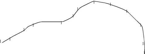
BRepTools_WireExplorer class can access edges of a wire in their order of connection.
For example, in the wire in the image we want to recuperate the edges in the order {e1, e2, e3,e4, e5} :
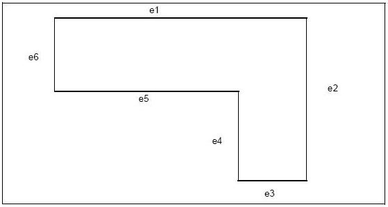
TopExp_Explorer, however, recuperates the lines in any order.
 1.8.5
1.8.5