 |
Open CASCADE Technology
7.8.0
|
|
 |
Open CASCADE Technology
7.8.0
|
|
This manual explains how to use the eXtended Data Exchange (XDE). It provides basic documentation on setting up and using XDE.
The Extended Data Exchange (XDE) module allows extending the scope of exchange by translating additional data attached to geometric BREP data, thereby improving the interoperability with external software.
Data types such as colors, layers, assembly descriptions and validation properties (i.e. center of gravity, etc.) are supported. These data are stored together with shapes in an XCAF document. It is also possible to add a new types of data taking the existing tools as prototypes.
Finally, the XDE provides reader and writer tools for reading and writing the data supported by XCAF to and from IGES and STEP files.
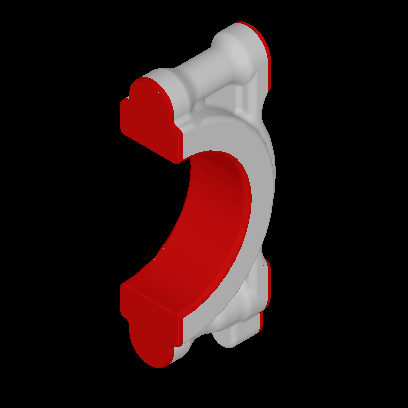
The XDE component requires Shape Healing toolkit for operation.
For better understanding of XDE, certain key terms are defined:
The basis of XDE, called XCAF, is a framework based on OCAF (Open CASCADE Technology Application Framework) and is intended to be used with assemblies and with various kinds of attached data (attributes). Attributes can be Individual attributes for a shape, specifying some characteristics of a shape, or they can be Grouping attributes, specifying that a shape belongs to a given group whose definition is specified apart from the shapes.
XDE works in an OCAF document with a specific organization defined in a dedicated XCAF module. This organization is used by various functions of XDE to exchange standardized data other than shapes and geometry.
The Assembly Structure and attributes assigned to shapes are stored in the OCAF tree. It is possible to obtain TopoDS representation for each level of the assembly in the form of TopoDS_Compound or TopoDS_Shape using the API.
Basic elements used by XDE are introduced in the XCAF sub-module by the package XCAFDoc. These elements consist in descriptions of commonly used data structures (apart from the shapes themselves) in normalized data exchanges. They are not attached to specific applications and do not bring specific semantics, but are structured according to the use and needs of data exchanges. The Document used by XDE usually starts as a TDocStd_Document.
XDE supports assemblies by separating shape definitions and their locations. Shapes are simple OCAF objects without a location definition. An assembly consists of several components. Each of these components references one and the same specified shape with different locations. All this provides an increased flexibility in working on multi-level assemblies.
For example, a mechanical assembly can be defined as follows:
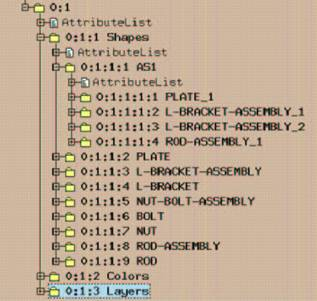
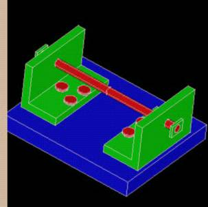
XDE defines the specific organization of the assembly content. Shapes are stored on sub-labels of label 0:1:1. There can be one or more roots (called free shapes) whether they are true trees or simple shapes. A shape can be considered to be an Assembly (such as AS1 under 0:1:1:1 in Figure1) if it is defined with Components (sub-shapes, located or not).
XCAFDoc_ShapeTool is a tool that allows managing the Shape section of the XCAF document. This tool is implemented as an attribute and located at the root label of the shape section.
Validation properties are geometric characteristics of Shapes (volume, centroid, surface area) written to STEP files by the sending system. These characteristics are read by the receiving system to validate the quality of the translation. This is done by comparing the values computed by the original system with the same values computed by the receiving system on the resulting model.
Advanced Data Exchange supports both reading and writing of validation properties, and provides a tool to check them.
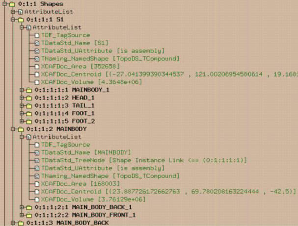
Check logs contain deviations of computed values from the values stored in a STEP file. A typical example appears as follows:
| Label | Area defect | Volume defect | dX | dY | dZ | Name |
|---|---|---|---|---|---|---|
0:1:1:1 | 312.6 (0%) | -181.7 (0%) | 0.00 | 0.00 | 0.00 | "S1" |
0:1:1:2 | -4.6 (0%) | -191.2 (0%) | -0.00 | 0.00 | -0.00 | "MAINBODY" |
0:1:1:3 | -2.3 (0%) | -52.5 (0%) | -0.00 | 0.00 | 0.00 | "MAIN_BODY_BACK" |
0:1:1:4 | -2.3 (0%) | -51.6 (0%) | 0.00 | 0.00 | -0.00 | "MAIN_BODY_FRONT" |
0:1:1:5 | 2.0 (0%) | 10.0 (0%) | -0.00 | 0.00 | -0.00 | "HEAD" |
0:1:1:6 | 0.4 (0%) | 0.0 (0%) | 0.00 | -0.00 | -0.00 | "HEAD_FRONT" |
0:1:1:7 | 0.4 (0%) | 0.0 (0%) | 0.00 | -0.00 | -0.00 | "HEAD_BACK" |
0:1:1:8 | -320.6 (0%) | 10.9 (0%) | -0.00 | 0.00 | 0.00 | "TAIL" |
0:1:1:9 | 0.0 (0%) | 0.0 (0%) | -0.00 | -0.00 | 0.00 | "TAIL_MIDDLE" |
0:1:1:10 | -186.2 (0%) | 4.8 (0%) | -0.00 | 0.00 | -0.00 | "TAIL_TURBINE" |
0:1:1:11 | 0.3 (0%) | -0.0 (0%) | -0.00 | -0.00 | 0.00 | "FOOT" |
0:1:1:12 | 0.0 (0%) | -0.0 (0%) | 0.00 | -0.00 | -0.00 | "FOOT_FRONT" |
0:1:1:13 | 0.0 (0%) | 0.0 (0%) | -0.00 | 0.00 | 0.00 | "FOOT_BACK" |
In our example, it can be seen that no errors were detected for either area, volume or positioning data.
XDE supports reading and writing the names of shapes to and from IGES and STEP file formats. This functionality can be switched off if you do not need this type of data, thereby reducing the size of the document.
XDE can read and write colors and layers assigned to shapes or their subparts (down to the level of faces and edges) to and from both IGES and STEP formats. Three types of colors are defined in the enumeration XCAFDoc_ColorType:
XCAFDoc_ColorGen)XCAFDoc_ColorSurf)XCAFDoc_ColorCurv)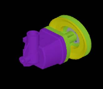
GD&T are a type of Product and Manufacturing Information (PMI) that can be either computed automatically by a CAD system, or entered manually by the user. For detailed information use CAx-IF Recommended Practices for the Representation and Presentation of Product Manufacturing Information (PMI) (AP242).
XDE can read and write GD&T data of the following types:
XDE supports two presentations of GD&T data:
XDE supports reading from STEP and storing named planes used for clipping. Currently, XDE supports saving of clipping planes in XBF format only.
XDE provides capabilities for adding, editing and removing clipping planes.
XDE supports reading from STEP views. Views allow saving information about camera parameters (position, direction, zoom factor, etc.) and visible shapes, PMIs, used clipping planes and notes. Currently, XDE supports saving of clipping planes in XBF format only.
XDE provides the following view management capabilities:
Custom notes is a kind of application-specific data attached to assembly items, their attributes and sub-shapes. Basically, there are simple textual comments, binary data and other application-specific data. Each note is provided with a timestamp and the user who created it.
Notes API provides the following functionality:
As explained in the last chapter, XDE uses TDocStd_Documents as a starting point. The general purpose of XDE is:
The Document used by XDE usually starts as a TDocStd_Document.
To use XDE you have to set the environment variables properly. Make sure that two important environment variables are set as follows:
CSF_PluginDefaults points to sources of $CASROOT/src/XCAFResources.CSF_XCAFDefaults points to sources of $CASROOT/src/XCAFResources.Before working with shapes, properties, and other types of information, the global organization of an XDE Document can be queried or completed to determine if an existing Document is actually structured for use with XDE.
To find out if an existing TDocStd_Document is suitable for XDE, use:
If the Document is suitable for XDE, you can perform operations and queries explained in this guide. However, if a Document is not fully structured for XDE, it must be initialized.
If you want to retrieve an existing application or an existing document (known to be correctly structured for XDE), use:
An XDE Document begins with a TDocStd_Document. Assuming you have a TDocStd_Document already created, you can ensure that it is correctly structured for XDE by initializing the XDE structure as follows:
Note that the method XCAFDoc_DocumentTool::ShapeTool returns the XCAFDoc_ShapeTool. The first time this method is used, it creates the XCAFDoc_ShapeTool. In our example, a handle is used for the TDocStd_Document.
To get a node considered as an Assembly from an XDE structure, you can use the Label of the node. Assuming that you have a properly initialized TDocStd_Document, use:
In the previous example, you can also get the Main Item of an XDE document, which records the root shape representation (as a Compound if it is an Assembly) by using XCAFDoc_DocumentTool::ShapeTool(theDoc->Main()) instead of XCAFDoc_DocumentTool::ShapeTool(aLabel).
You can then query or edit this Assembly node, the Main Item or another one (myAssembly in our examples).
Note that for the examples in the rest of this guide, myAssembly is always presumed to be accessed this way, so this information will not be repeated.
Some actions in this chapter affect the content of the document, considered as an Assembly. As a result, you will sometimes need to update various representations (including the compounds).
To update the representations, use:
This call performs a top-down update of the Assembly compounds stored in the document.
Note that you have to run this method manually to actualize your Assemblies after any low-level modifications on shapes.
Shapes can be added as top-level shapes. Top level means that they can be added to an upper level assembly or added on their own at the highest level as a component or referred by a located instance. Therefore two types of top-level shapes can be added:
Note that several top-level shapes can be added to the same component.
A shape to be added can be defined as a compound (if required), with the following interpretations:
To break down a Compound in the assembly structure, use:
Each node of the assembly therefore refers to its sub-shapes.
Concerning located instances of sub-shapes, the corresponding shapes (without location) appear at distinct sub-labels. They are referred to by a shape instance, which associates a location.
A top-level shape can be changed. In this example, no interpretation of compound is performed:
To get a shape from its Label from the top-level, use:
Note that if the label corresponds to an assembly, the result is a compound.
To get a Label, which is attached to a Shape from the top-level, use:
If toFindInstance is True, a search is made for the shape with the same location. If it is False (default value), a search is made among original, non-located shapes.
Various other queries can be made from a Label within the Main Item of XDE:
To determine if a Shape is recorded (or not), use:
To determine if the shape is top-level, i.e. was added by the XCAFDoc_ShapeTool::AddShape method, use:
To get a list of top-level shapes added by the XCAFDoc_ShapeTool::AddShape method, use:
To get all free shapes at once if the list above has only one item, use:
If there is more than one item, you must create and fill a compound, use:
In our example, the result is the compound aComp. To determine if a shape is a free shape (no reference or super-assembly), use:
To get a list of Free Shapes (roots), use:
To get the shapes, which use a given shape as a component, use:
The count of aUsers is contained with aNbUsers. It contains 0 if there are no users.
To determine if a label is attached to the main part or to a sub-part (component), use:
To determine whether a label is a node of a (sub-) assembly or a simple shape, use:
If the label is a node of a (sub-) assembly, you can get the count of components, use:
If subchilds is True, commands also consider sub-levels. By default, only level one is checked.
To get component Labels themselves, use:
To determine if a label is a simple shape, use:
To determine if a label is a located reference to another one, use:
If the label is a located reference, you can get the location, use:
To get the label of a referenced original shape (also tests if it is a reference), use:
Note isRef returns False if aLabel is not for a reference.
In addition to the previously described AddShape and SetShape, several shape edits are possible.
To remove a Shape, and all its sub-labels, use:
This operation will fail if the shape is neither free nor top level.
To add a Component to the Assembly, from a new shape, use:
If toExpand is True and aShape is a Compound, aShape is broken down to produce sub-components, one for each of its sub-shapes.
To add a component to the assembly, from a previously recorded shape (the new component is defined by the label of the reference shape, and its location), use:
To remove a component from the assembly, use:
In addition to components of a (sub-)assembly, it is possible to have individual identification of some sub-shapes inside any shape. Therefore, you can attach specific attributes such as Colors. Some additional actions can be performed on sub-shapes that are neither top-level, nor components. To add a sub-shape to a given Label, use:
To find the Label attached to a given sub-shape, use:
If the sub-shape is found (yes), aSubLabel is filled by the correct value.
To find the top-level simple shape (not a compound whether free or not), which contains a given sub-shape, use:
Note that there should be only one shape for a valid model. In any case, the search stops on the first one found.
To get the sub-shapes of a shape, which are recorded under a label, use:
Some properties can be attached directly to shapes. These properties are:
Some other properties can also be attached, and are also managed by distinct tools for Colors and Layers. Colors and Layers are managed as an alternative way of organizing data (by providing a way of identifying groups of shapes). Colors are put into a table of colors while shapes refer to this table.
There are two ways of attaching a color to a shape:
When the color is added directly, a search is performed in the table of contents to determine if it contains the requested color. Once this search and initialize operation is done, the first way of attaching a color to a shape is used.
Name is implemented and used as a TDataStd_Name, which can be attached to any label. Before proceeding, consider that:
MYCURVE is a name, and MYCURVE(60) is a name with a Subscript Label.Note that both IGES or STEP files handle names as pure ASCII strings.
These considerations are not specific to XDE. What is specific to data exchange is the way names are attached to entities.
To get the name attached to a label (as a reminder using OCAF), use:
Don't forget to consider Extended String as ASCII, for the exchange file.
To set a name to a label (as a reminder using OCAF), use:
A Centroid is defined by a Point to fix its position. It is handled as a property, item of the class XCAFDoc_Centroid, sub-class of TDF_Attribute. However, global methods give access to the position itself.
This notion has been introduced in STEP, together with that of Volume, and Area, as defining the Validation Properties: this feature allows exchanging the geometries and some basic attached values, in order to perform a synthetic checking on how they are maintained after reading and converting the exchange file. This exchange depends on reliable exchanges of Geometry and Topology. Otherwise, these values can be considered irrelevant.
A centroid can be determined at any level of an assembly, thereby allowing a check of both individual simple shapes and their combinations including locations.
To get a Centroid attached to a Shape, use:
To set a Centroid to a Shape, use:
An Area is defined by a Real, it corresponds to the computed Area of a Shape, provided that it contains surfaces. It is handled as a property, item of the class XCAFDoc_Area, sub-class of TDF_Attribute. This notion has been introduced in STEP but it is usually disregarded for a Solid, as Volume is used instead. In addition, it is attached to simple shapes, not to assemblies.
To get an area attached to a Shape, use:
To set an area value to a Shape, use:
A Volume is defined by a Real and corresponds to the computed volume of a Shape, provided that it contains solids. It is handled as a property, an item of the class XCAFDoc_Volume, sub-class of TDF_Attribute. This notion has been introduced in STEP. It may be attached to simple shapes or their assemblies for computing cumulated volumes and centers of gravity.
To get a Volume attached to a Shape, use:
To set a volume value to a Shape, use:
XDE can read and write colors and layers assigned to shapes or their subparts (down to level of faces and edges) to and from both IGES and STEP formats.
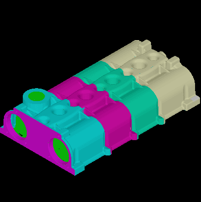
In an XDE document, colors are managed by the class XCAFDoc_ColorTool. It works basing on the same principles as ShapeTool works with Shapes. This tool can be provided on the Main Label or on any sub-label. The Property itself is defined as an XCAFDoc_Color, sub-class of TDF_Attribute.
Colors are stored in a child of the starting document label: it is the second level (0.1.2), while Shapes are at the first level. Each color then corresponds to a dedicated label, the property itself is a Quantity_Color, which has a name and value for Red, Green, Blue. A Color may be attached to Surfaces (flat colors) or to Curves (wireframe colors), or to both. A Color may be attached to a sub-shape. In such a case, the sub-shape (and its own sub-shapes) takes its own Color as a priority.
Layers are handled using the same principles as Colors. In all operations described below you can simply replace Color with Layer when dealing with Layers. Layers are supported by the class XCAFDoc_LayerTool.
The class of the property is XCAFDoc_Layer, sub-class of TDF_Attribute while its definition is a TCollection_ExtendedString. Integers are generally used when dealing with Layers. The general cases are:
Colors and Shapes are related to by Tree Nodes.
These definitions are common to various exchange formats, at least for STEP and IGES.
To query, edit, or initialize a Document to handle Colors of XCAF, use:
This call can be used at any time. The first time it is used, a relevant structure is added to the document. This definition is used for all the following color calls and will not be repeated for these.
There are two ways to add a color. You can:
Quantity_Color and then directly set it to a Shape (anonymous Color);When the Color is added by its value Quantity_Color, it is added only if it has not yet been recorded (same RGB values) in the Document.
To set a Color to a Shape using a label, use:
Alternately, the Shape can be designated directly, without using its label, use:
Note that this Color can then be named, allowing later retrieval by its Name instead of its Value.
To set a Color, identified by its Label and already recorded, to a Shape, use:
In this example, aLabel can be replaced by aShape directly.
Various queries can be performed on colors. However, only specific queries are included in this section, not general queries using names.
To determine if a Color is attached to a Shape, for a given color type (aColType), use:
In this example, aLabel can be replaced by aShape directly.
To get the Color attached to a Shape (for any color type), use:
Color name can also be queried from aCol.StringName or aCol.Name. In this example, aLabel can be replaced by aShape directly.
To get the Color attached to a Shape, with a specific color type, use:
To get all the Colors recorded in the Document, use:
To find a Color from its Value, use:
Besides adding colors, the following attribute edits can be made:
To unset a Color on a Shape, use:
To remove a Color and all the references to it (so that the related shapes will become colorless), use:
XDE can read and write GD&T assigned to shapes or their subparts (down to the level of faces and edges) to and from STEP formats.
In an XDE document, GD&T are managed by the class XCAFDoc_DimTolTool. It works basing on the same principles as ShapeTool works with Shapes. This tool can be provided on the Main Label or on any sub-label. The GD&T entities themselves are defined as the following sub-classes of TDF_Attribute:
XCAFDoc_Dimension - for dimensions;XCAFDoc_GeomTolerance - for geometric tolerances;XCAFDoc_Datum - for geometric tolerance Datums.A GD&T type is identified by the attributes listed above, i.e. XCAFDoc_DimTolTool methods working with particular entity types check for presence of the corresponding attributes in passed labels. One can use methods of XCAFDoc_DimTolTool beginning with 'Is' for this purpose.
GD&T entities are stored in a child of the starting document label 0.1.4. Each GD&T entity then corresponds to the dedicated label, the property itself is one of access classes:
XCAFDimTolObject_DimensionObject - for dimensions;XCAFDimTolObject_GeomToleranceObject - for geometric tolerances;XCAFDimTolObject_DatumObject - for geometric tolerance Datums.GD&Ts and Shapes are related by Graph Nodes.
These definitions are common to various exchange formats, at least for STEP.
To query, edit, or initialize a Document to handle GD&Ts of XCAF, use:
This call can be used at any time. When it is used for the first time, a relevant structure is added to the document. This definition is used for all later GD&T calls and is not repeated for them.
XCAFDoc_DimTolTool provides methods to create GD&T 'empty' entities:
XCAFDoc_DimTolTool::AddDimension - for a new dimension;XCAFDoc_DimTolTool::AddGeomTolerance - for a new geometric tolerance;XCAFDoc_DimTolTool::AddDatum - for a new geometric tolerance datum.All methods create a sub-label for the corresponding GD&T entity of the tool master label and attach an attribute specific for the created entity.
Here is an example of adding a new dimension:
A similar approach can be used for other GD&T types.
A newly added GD&T entity is empty. To set its data a corresponding access object should be used as it is demonstrated below, where the dimension becomes a linear distance between two points.
A similar approach can be used for other GD&T types.
To link a GD&T entity with other OCAF labels (e.g. representing shapes) one should use the following methods:
XCAFDoc_DimTolTool::SetDimension - for dimensions;XCAFDoc_DimTolTool::SetGeomTolerance - for geometric tolerances;XCAFDoc_DimTolTool::SetDatum - for geometric tolerance datums.These methods can take a single label or a sequence of labels. All previous links will be removed.
The example below demonstrates linking of a dimension to sequences of shape labels:
In addition, a special method XCAFDoc_DimTolTool::SetDatumToGeomTol should be used to link a datum with a geometric tolerance.
XCAFDimTolObjects_Tool class provides basic capabilities for searching GD&Ts linked to shapes. The tool provides sequences of dimensions, geometric tolerances and datums linked with a shape. A series of related datums is also returned for geometric tolerances.
To get reference shapes for a GD&T entity one can use XCAFDoc_DimTolTool::GetRefShapeLabel.
XCAFDoc_DimTolTool provides methods to get lists of all dimensions, geometric tolerances and datums.
Every GD&T entity in XDE is represented as a label with attached attribute identifying entity type. All specific data is stored in sub-labels in standard OCAF attributes, such as TDataStd_Integer, TDataStd_IntegerArray, TDataStd_RealArray and so on. Sub-label tags are reserved for internal use and cannot be used for storing custom data. The following tag ranges are reserved for GD&T entities:
Custom data can be stored in labels with tags beyond the ranges listed above.
In an XDE document, Clipping planes are managed by the class XCAFDoc_ClippingPlaneTool. It works basing on the same principles as ShapeTool works with Shapes. This tool can be provided on the Main Label or on any sub-label. Clipping planes are stored in a child of the starting document label 0.1.8, where planes themselves are defined as TDataXtd_Plane attribute. TDataStd_Name attribute is used for naming.
To query, edit, or initialize a Document to handle clipping planes of XCAF, use:
This call can be used at any time. When it is used for the first time, a relevant structure is added to the document.
To add a clipping plane use one of overloaded methods XCAFDoc_ClippingPlaneTool::AddClippingPlane, e.g.:
To remove a plane use XCAFDoc_ClippingPlaneTool::RemoveClippingPlane method, e.g.:
The plane will not be removed if it is referenced in at least one view.
To change the clipping plane and its name use XCAFDoc_ClippingPlaneTool::UpdateClippingPlane method, e.g.:
Capping property can be changed using XCAFDoc_ClippingPlaneTool::SetCapping method, e.g.:
XCAFDoc_ClippingPlaneTool can be used to get all clipping plane labels and to check if a label belongs to the ClippingPlane table, e.g.:
In an XDE document, Views are managed by the class XCAFDoc_ViewTool. It works basing on the same principles as ShapeTool works with Shapes. This tool can be provided on the Main Label or on any sub-label. Views are stored in a child of the starting document label 0.1.7, where a view itself is defined as XCAFDoc_View sub-class of TDF_Attribute. Views and selected shapes, clipping planes, GD&Ts and notes are related by Graph Nodes.
To query, edit, or initialize a Document to handle views of XCAF, use:
This call can be used at any time. When it is used for the first time, a relevant structure is added to the document.
To add a view use XCAFDoc_ViewTool::AddView method and an access XCAFView_Object object to set camera parameters, e.g.:
To set shapes, clipping planes, GD&Ts and notes selected for the view use one of overloaded SetView methods of XCAFDoc_ViewTool. To set only clipping planes one should use XCAFDoc_ViewTool::SetClippingPlanes method.
To remove a view use XCAFDoc_ViewTool::RemoveView method.
To get all view labels and check if a label belongs to the View table use:
To get shapes, clipping planes, GD&Ts or notes associated with a particular view use the following methods:
XCAFDoc_ViewTool::GetRefShapeLabel - returns a sequence of associated shape labels;XCAFDoc_ViewTool::GetRefGDTLabel - returns a sequence of associated GDT labels;XCAFDoc_ViewTool::GetRefClippingPlaneLabel - returns a sequence of associated clipping plane labels;XCAFDoc_ViewTool::GetRefNoteLabel - returns a sequence of associated note labels;XCAFDoc_ViewTool::GetRefAnnotationLabel - returns a sequence of associated annotated labels.And vice versa, to get views that display a particular clipping plane, GD&T or note use the following methods:
XCAFDoc_ViewTool::GetViewLabelsForShape - returns a sequence of view labels associated with a shape;XCAFDoc_ViewTool::GetViewLabelsForGDT - returns a sequence of view labels associated with a GD&T;XCAFDoc_ViewTool::GetViewLabelsForClippingPlane - returns a sequence of view labels associated with a clipping plane;XCAFDoc_ViewTool::GetViewLabelsForNote - returns a sequence of view labels associated with a note;XCAFDoc_ViewTool::GetViewLabelsForAnnotation - returns a sequence of view labels associated with an annotated label.In an XDE document, custom notes are managed by the class XCAFDoc_NotesTool. It works basing on the same principles as ShapeTool works with Shapes. This tool can be provided on the Main Label or on any sub-label. The Property itself is defined as sub-class of XCAFDoc_Note abstract class, which is a sub-class of TDF_Attribute one.
Custom notes are stored in a child of the XCAFDoc_NotesTool label, at label 0.1.9.1. Each note then corresponds to a dedicated label. A note may be attached to a document item identified by a label, a sub-shape identified by integer index or an attribute identified by GUID. Annotations are stored in a child of the XCAFDoc_NotesTool label, at label 0.1.9.2. Notes binding is done through XCAFDoc_GraphNode attribute.
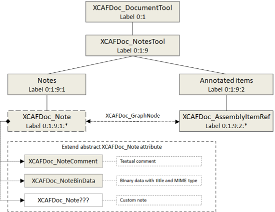
To query, edit, or initialize a Document to handle custom notes of XCAF, use:
This call can be used at any time. The first time it is used, a relevant structure is added to the document. This definition is used for all later notes calls and will not be repeated for them.
Before annotating a Document item a note must be created using one of the following methods of XCAFDoc_NotesTool class:
XCAFDoc_NotesTool::CreateComment: creates a note with a textual comment;XCAFDoc_NotesTool::CreateBinData: creates a note with arbitrary binary data, e.g. contents of a file.Both methods return an instance of XCAFDoc_Note class.
This code adds a child label to label 0.1.9.1 with XCAFDoc_NoteComment attribute.
An instance of XCAFDoc_Note class can be used for note editing. One may change common note data.
To change specific data one needs to down cast myNote handle to the appropriate sub-class:
In order to edit auxiliary note data such as text and attachment position, plane for rendering and tessellated presentation, one should use a transfer object XCAFNoteObjects_NoteObject by GetObject and SetObject methods of XCAFDoc_Note class. XCAFNoteObjects_NoteObject class provides the following functionality:
HasPlane, GetPlane and SetPlane methods test, get and set plane for note rendering;HasPoint, GetPoint and SetPoint methods test, get and set note attachment position on the annotated object;HasPointText, GetPointText, SetPointText methods test, get and set test position;GetPresentation and SetPresentation methods allow to test for and specify tessellated presentation.After getting, the transfer object can be edited and set back to the note:
Once a note has been created it can be bound to a Document item using the following XCAFDoc_NotesTool methods:
XCAFDoc_NotesTool::AddNote: binds a note to a label;XCAFDoc_NotesTool::AddNoteToAttr: binds a note to a label's attribute;XCAFDoc_NotesTool::AddNoteToSubshape: binds a note to a sub-shape.All methods return a pointer to XCAFDoc_AssemblyItemRef attribute identifying the annotated item.
This code adds three child labels with XCAFDoc_AssemblyItemRef attribute to label 0.1.9.2. XCAFDoc_GraphNode attributes are added to the child labels and note labels.
To find annotation labels under label 0.1.9.2 use the following XCAFDoc_NotesTool methods:
XCAFDoc_NotesTool::FindAnnotatedItem: returns an annotation label for a label;XCAFDoc_NotesTool::FindAnnotatedItemAttr: returns an annotation label for a label's attribute;XCAFDoc_NotesTool::FindAnnotatedItemSubshape: returns an annotation label for a sub-shape.Null label will be returned if there is no corresponding annotation.
To get all notes of the Document item use the following XCAFDoc_NotesTool methods:
XCAFDoc_NotesTool::GetNotes: outputs a sequence of note labels bound to a label;XCAFDoc_NotesTool::GetAttrNotes: outputs a sequence of note labels bound to a label's attribute;XCAFDoc_NotesTool::GetAttrSubshape: outputs a sequence of note labels bound to a sub-shape.All these methods return the number of notes.
To remove a note use one of the following XCAFDoc_NotesTool methods:
XCAFDoc_NotesTool::RemoveNote: unbinds a note from a label;XCAFDoc_NotesTool::RemoveAttrNote: unbinds a note from a label's attribute;XCAFDoc_NotesTool::RemoveSubshapeNote: unbinds a note from a sub-shape.A note will not be deleted automatically. Counterpart methods to remove all notes are available, too.
To delete note(s) use the following XCAFDoc_NotesTool methods:
XCAFDoc_NotesTool::DeleteNote: deletes a single note;XCAFDoc_NotesTool::DeleteNotes: deletes a sequence of notes;XCAFDoc_NotesTool::DeleteAllNotes: deletes all Document notes;XCAFDoc_NotesTool::DeleteOrphanNotes: deletes notes not bound to Document items.All these methods except for the last one break all links with Document items as well.
Note that saving and restoring the document itself are standard OCAF operations. As the various previously described definitions enter into this frame, they will not be explained any further. The same can be said for Viewing: presentations can be defined from Shapes and Colors.
There are several important points to consider:
The packages to manage this are IGESCAFControl for IGES, and STEPCAFControl for STEP.
To read a STEP file by itself, use:
In addition, the reader provides methods that are applicable to document transfers and for directly querying of the data produced.
To write a STEP file by itself, use:
Use the same procedure as for a STEP file but with IGESCAFControl instead of STEPCAFControl.
Use the same procedure as for a STEP file but with IGESCAFControl instead of STEPCAFControl.
There are several ways of exploiting XDE data from an application, you can:
To have XCAF data elsewhere than under label 0.1, you use the DocLabel of XDE. The method XCAFDoc_DocumentTool::DocLabel determines the relevant Label for XCAF. However, note that the default is 0.1.
In addition, as XDE data is defined and managed in a modular way, you can consider exclusively Assembly Structure, only Colors, and so on.
As XDE provides an extension of the data structure, for relevant data in standardized exchanges, note the following:
As a result, if an application works on Assemblies, on Colors or Layers, on Validation Properties (as defined in STEP), it can rely on all or a part of the XDE definitions, and include them in its own data structure.
In addition, if an application has a data structure far from these notions, it can get data (such as Colors and Names on Shapes) according to its needs, but without having to consider the whole.