 |
Open CASCADE Technology
7.7.0
|
|
 |
Open CASCADE Technology
7.7.0
|
|
This manual explains how to use the Modeling Algorithms. It provides basic documentation on modeling algorithms.
The Modeling Algorithms module brings together a wide range of topological algorithms used in modeling. Along with these tools, you will find the geometric algorithms, which they call.
Open CASCADE Technology geometric tools provide algorithms to:
The Intersections component is used to compute intersections between 2D or 3D geometrical objects:
The Geom2dAPI_InterCurveCurve class allows the evaluation of the intersection points (gp_Pnt2d) between two geometric curves (Geom2d_Curve) and the evaluation of the points of self-intersection of a curve.
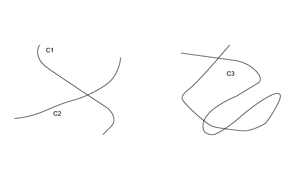
In both cases, the algorithm requires a value for the tolerance (Standard_Real) for the confusion between two points. The default tolerance value used in all constructors is 1.0e-6.
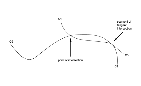
The algorithm returns a point in the case of an intersection and a segment in the case of tangent intersection.
Geom2dAPI_InterCurveCurve class may be instantiated for intersection of curves C1 and C2.
or for self-intersection of curve C3.
Calls the number of intersection points
To select the desired intersection point, pass an integer index value in argument.
To call the number of intersection segments, use
To select the desired intersection segment pass integer index values in argument.
If you need access to a wider range of functionalities the following method will return the algorithmic object for the calculation of intersections:
The GeomAPI_IntCS class is used to compute the intersection points between a curve and a surface.
This class is instantiated as follows:
To call the number of intersection points, use:
Where Index is an integer between 1 and nb, calls the intersection points.
The GeomAPI_IntSS class is used to compute the intersection of two surfaces from Geom_Surface with respect to a given tolerance.
This class is instantiated as follows:
Once the GeomAPI_IntSS object has been created, it can be interpreted.
Calls the number of intersection curves.
Where Index is an integer between 1 and nb, calls the intersection curves.
The Interpolation Laws component provides definitions of functions: y=f(x) .
In particular, it provides definitions of:
Such functions can be used to define, for example, the evolution law of a fillet along the edge of a shape.
The validity of the function built is never checked: the Law package does not know for what application or to what end the function will be used. In particular, if the function is used as the evolution law of a fillet, it is important that the function is always positive. The user must check this.
This class is used to interpolate a BSplineCurve passing through an array of points. If tangency is not requested at the point of interpolation, continuity will be C2. If tangency is requested at the point, continuity will be C1. If Periodicity is requested, the curve will be closed and the junction will be the first point given. The curve will then have a continuity of C1 only. This class may be instantiated as follows:
It is possible to call the BSpline curve from the object defined above it.
Note that the Handle(Geom2d_BSplineCurve) operator has been redefined by the method Curve(). Consequently, it is unnecessary to pass via the construction of an intermediate object of the Geom2dAPI_Interpolate type and the following syntax is correct.
This class may be instantiated as follows:
It is possible to call the BSpline curve from the object defined above it.
Note that the Handle(Geom_BSplineCurve) operator has been redefined by the method Curve(). Thus, it is unnecessary to pass via the construction of an intermediate object of the GeomAPI_Interpolate type and the following syntax is correct.
Handle(Geom_BSplineCurve) C = GeomAPI_Interpolate(Points, Standard_False, 1.0e-7);
Boundary conditions may be imposed with the method Load.
The algorithms for construction of 2D circles or lines can be described with numeric or geometric constraints in relation to other curves.
These constraints can impose the following :
For example, these algorithms enable to easily construct a circle of a given radius, centered on a straight line and tangential to another circle.
The implemented algorithms are more complex than those provided by the Direct Constructions component for building 2D circles or lines.
The expression of a tangency problem generally leads to several results, according to the relative positions of the solution and the circles or straight lines in relation to which the tangency constraints are expressed. For example, consider the following case of a circle of a given radius (a small one) which is tangential to two secant circles C1 and C2:
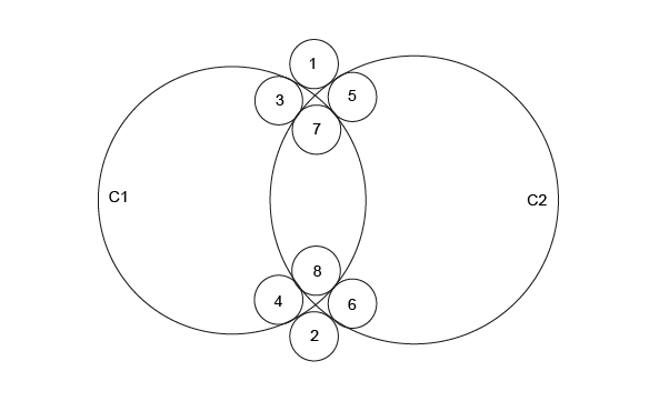
This diagram clearly shows that there are 8 possible solutions.
In order to limit the number of solutions, we can try to express the relative position of the required solution in relation to the circles to which it is tangential. For example, if we specify that the solution is inside the circle C1 and outside the circle C2, only two solutions referenced 3 and 4 on the diagram respond to the problem posed.
These definitions are very easy to interpret on a circle, where it is easy to identify the interior and exterior sides. In fact, for any kind of curve the interior is defined as the left-hand side of the curve in relation to its orientation.
This technique of qualification of a solution, in relation to the curves to which it is tangential, can be used in all algorithms for constructing a circle or a straight line by geometric constraints. Four qualifiers are used:
It is possible to create expressions using the qualifiers, for example:
This expression finds all circles of radius Rad, which are tangent to both circle C1 and C2, while C1 is outside and C2 is inside.
The following analytic algorithms using value-handled entities for creation of 2D lines or circles with geometric constraints are available:
It is not hard to define the interior and exterior of a circle. As is shown in the following diagram, the exterior is indicated by the sense of the binormal, that is to say the right side according to the sense of traversing the circle. The left side is therefore the interior (or "material").
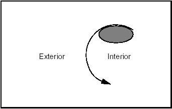
By extension, the interior of a line or any open curve is defined as the left side according to the passing direction, as shown in the following diagram:
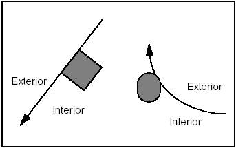
It is sometimes necessary to define in advance the sense of travel along a line to be created. This sense will be from first to second argument.
The following figure shows a line, which is first tangent to circle C1 which is interior to the line, and then passes through point P1.
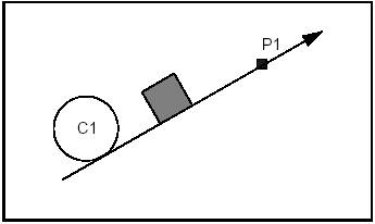
The following four diagrams illustrate four cases of using qualifiers in the creation of a line. The fifth shows the solution if no qualifiers are given.
Example 1 Case 1
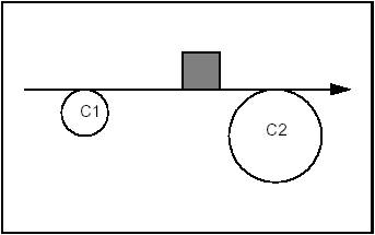
Constraints: Tangent and Exterior to C1. Tangent and Exterior to C2.
Syntax:
Example 1 Case 2
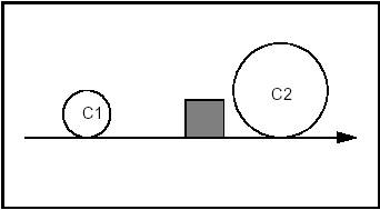
Constraints: Tangent and Including C1. Tangent and Including C2.
Syntax:
Example 1 Case 3
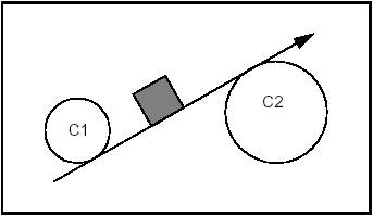
Constraints: Tangent and Including C1. Tangent and Exterior to C2.
Syntax:
Example 1 Case 4
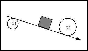
Constraints: Tangent and Exterior to C1. Tangent and Including C2.
Syntax:
Example 1 Case 5
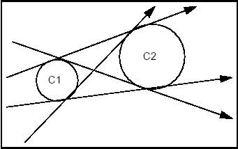
Constraints: Tangent and Undefined with respect to C1. Tangent and Undefined with respect to C2.
Syntax:
The following four diagrams show the four cases in using qualifiers in the creation of a circle.
Example 2 Case 1
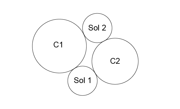
Constraints: Tangent and Exterior to C1. Tangent and Exterior to C2.
Syntax:
Example 2 Case 2
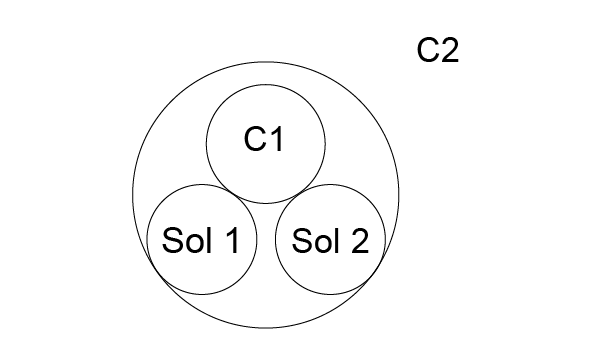
Constraints: Tangent and Exterior to C1. Tangent and Included by C2.
Syntax:
Example 2 Case 3
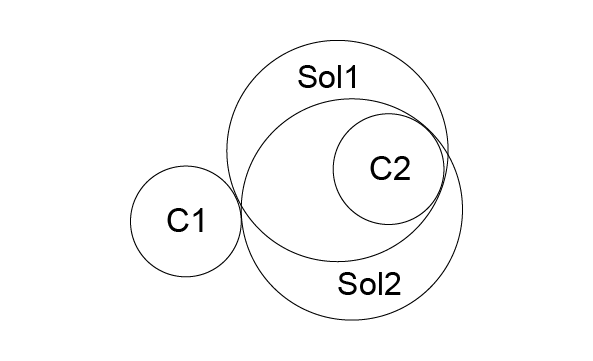
Constraints: Tangent and Exterior to C1. Tangent and Including C2.
Syntax:
Example 2 Case 4
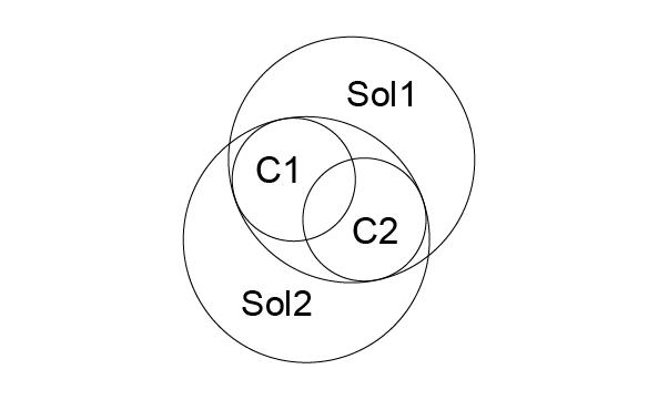
Constraints: Tangent and Enclosing C1. Tangent and Enclosing C2.
Syntax:
Example 2 Case 5
The following syntax will give all the circles of radius Rad, which are tangent to C1 and C2 without discrimination of relative position:
OCCT implements several categories of algorithms:
For each kind of geometric construction of a constrained line or circle, OCCT provides two types of access:
The provided algorithms compute all solutions, which correspond to the stated geometric problem, unless the solution is found by an iterative algorithm.
Iterative algorithms compute only one solution, closest to an initial position. They can be used in the following cases:
Qualified curves (for tangency arguments) are provided either by:
The GccEnt and Geom2dGcc packages also provide simple functions for building qualified curves in a very efficient way.
The GccAna package also provides algorithms for constructing bisecting loci between circles, lines or points. Bisecting loci between two geometric objects are such that each of their points is at the same distance from the two geometric objects. They are typically curves, such as circles, lines or conics for GccAna algorithms. Each elementary solution is given as an elementary bisecting locus object (line, circle, ellipse, hyperbola, parabola), described by the GccInt package.
Note: Curves used by GccAna algorithms to define the geometric problem to be solved, are 2D lines or circles from the gp package: they are not explicitly parameterized. However, these lines or circles retain an implicit parameterization, corresponding to that which they induce on equivalent Geom2d objects. This induced parameterization is the one used when returning parameter values on such curves, for instance with the functions Tangency1, Tangency2, Tangency3, Intersection2 and CenterOn3 provided by construction algorithms from the GccAna or Geom2dGcc packages.
The Curves and Surfaces from Constraints component groups together high level functions used in 2D and 3D geometry for:
OPEN CASCADE company also provides a product known as Surfaces from Scattered Points, which allows constructing surfaces from scattered points. This algorithm accepts or constructs an initial B-Spline surface and looks for its deformation (finite elements method) which would satisfy the constraints. Using optimized computation methods, this algorithm is able to construct a surface from more than 500 000 points.
SSP product is not supplied with Open CASCADE Technology, but can be purchased separately.
Elastic beam curves have their origin in traditional methods of modeling applied in boat-building, where a long thin piece of wood, a lathe, was forced to pass between two sets of nails and in this way, take the form of a curve based on the two points, the directions of the forces applied at those points, and the properties of the wooden lathe itself.
Maintaining these constraints requires both longitudinal and transversal forces to be applied to the beam in order to compensate for its internal elasticity. The longitudinal forces can be a push or a pull and the beam may or may not be allowed to slide over these fixed points.
The class FairCurve_Batten allows producing faired curves defined on the basis of one or more constraints on each of the two reference points. These include point, angle of tangency and curvature settings. The following constraint orders are available:
Only 0 and 1 constraint orders are used. The function Curve returns the result as a 2D BSpline curve.
The class FairCurve_MinimalVariation allows producing curves with minimal variation in curvature at each reference point. The following constraint orders are available:
Constraint orders of 0, 1 and 2 can be used. The algorithm minimizes tension, sagging and jerk energy.
The function Curve returns the result as a 2D BSpline curve.
If you want to give a specific length to a batten curve, use:
where b is the name of the batten curve object
Free sliding is generally more aesthetically pleasing than constrained sliding. However, the computation can fail with values such as angles greater than p/2 because in this case the length is theoretically infinite.
In other cases, when sliding is imposed and the sliding factor is too large, the batten can collapse.
The constructor parameters, Tolerance and NbIterations, control how precise the computation is, and how long it will take.
A ruled surface is built by ruling a line along the length of two curves.
The class GeomFill_BezierCurves allows producing a Bezier surface from contiguous Bezier curves. Note that problems may occur with rational Bezier Curves.
The class GeomFill_BSplineCurves allows producing a BSpline surface from contiguous BSpline curves. Note that problems may occur with rational BSplines.
The class GeomFill_Pipe allows producing a pipe by sweeping a curve (the section) along another curve (the path). The result is a BSpline surface.
The following types of construction are available:
It is often convenient to create a surface from some curves, which will form the boundaries that define the new surface. This is done by the class GeomFill_ConstrainedFilling, which allows filling a contour defined by three or four curves as well as by tangency constraints. The resulting surface is a BSpline.
A case in point is the intersection of two fillets at a corner. If the radius of the fillet on one edge is different from that of the fillet on another, it becomes impossible to sew together all the edges of the resulting surfaces. This leaves a gap in the overall surface of the object which you are constructing.
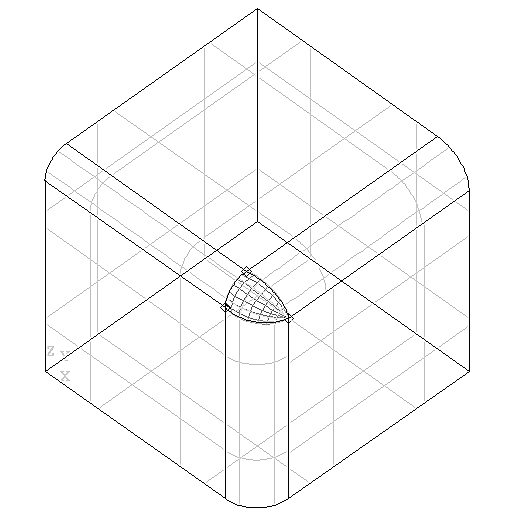
These algorithms allow you to fill this gap from two, three or four curves. This can be done with or without constraints, and the resulting surface will be either a Bezier or a BSpline surface in one of a range of filling styles.
The class GeomFill_SimpleBound allows you defining a boundary for the surface to be constructed.
The class GeomFill_BoundWithSurf allows defining a boundary for the surface to be constructed. This boundary will already be joined to another surface.
The enumerations FillingStyle specify the styles used to build the surface. These include:
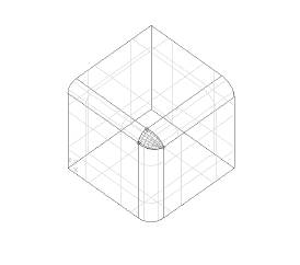
In CAD, it is often necessary to generate a surface which has no exact mathematical definition, but which is defined by respective constraints. These can be of a mathematical, a technical or an aesthetic order.
Essentially, a plate surface is constructed by deforming a surface so that it conforms to a given number of curve or point constraints. In the figure below, you can see four segments of the outline of the plane, and a point which have been used as the curve constraints and the point constraint respectively. The resulting surface can be converted into a BSpline surface by using the function MakeApprox .
The surface is built using a variational spline algorithm. It uses the principle of deformation of a thin plate by localised mechanical forces. If not already given in the input, an initial surface is calculated. This corresponds to the plate prior to deformation. Then, the algorithm is called to calculate the final surface. It looks for a solution satisfying constraints and minimizing energy input.
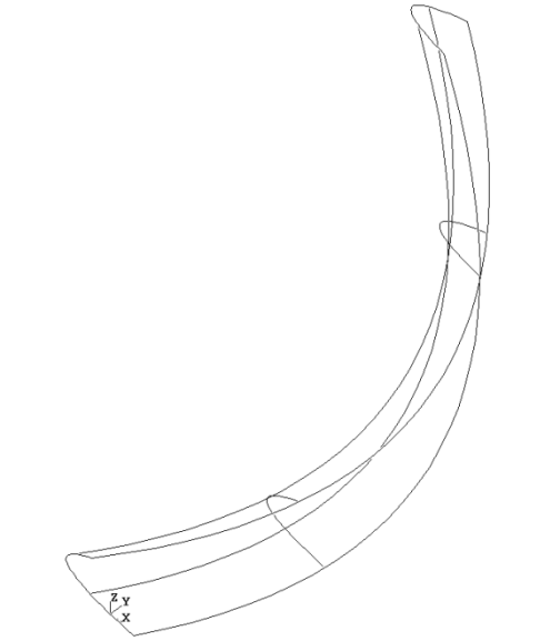
The package GeomPlate provides the following services for creating surfaces respecting curve and point constraints:
The class BuildPlateSurface allows creating a framework to build surfaces according to curve and point constraints as well as tolerance settings. The result is returned with the function Surface.
Note that you do not have to specify an initial surface at the time of construction. It can be added later or, if none is loaded, a surface will be computed automatically.
The class CurveConstraint allows defining curves as constraints to the surface, which you want to build.
The class PointConstraint allows defining points as constraints to the surface, which you want to build.
The class Surface allows describing the characteristics of plate surface objects returned by BuildPlateSurface::Surface using the methods of Geom_Surface
The class MakeApprox allows converting a GeomPlate surface into a Geom_BSplineSurface.
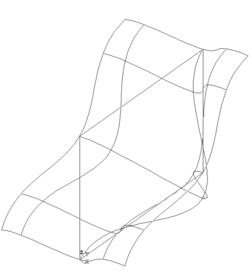
Let us create a Plate surface and approximate it from a polyline as a curve constraint and a point constraint
Projections provide for computing the following:
Geom2dAPI_ProjectPointOnCurve allows calculation of all normals projected from a point (gp_Pnt2d) onto a geometric curve (Geom2d_Curve). The calculation may be restricted to a given domain.
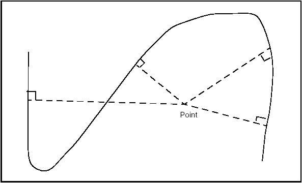
The curve does not have to be a Geom2d_TrimmedCurve. The algorithm will function with any class inheriting Geom2d_Curve.
The class Geom2dAPI_ProjectPointOnCurve may be instantiated as in the following example:
To restrict the search for normals to a given domain [U1,U2], use the following constructor:
Having thus created the Geom2dAPI_ProjectPointOnCurve object, we can now interrogate it.
The solutions are indexed in a range from 1 to Projector.NbPoints(). The point, which corresponds to a given Index may be found:
For a given point corresponding to a given Index:
This can also be programmed as:
We can find the distance between the initial point and a point, which corresponds to the given Index:
This class offers a method to return the closest solution point to the starting point. This solution is accessed as follows:
Some operators have been redefined to find the closest solution.
Standard_Real() returns the minimum distance from the point to the curve.
Standard_Integer() returns the number of solutions.
gp_Pnt2d() returns the nearest solution point.
Using these operators makes coding easier when you only need the nearest point. Thus:
can be written more concisely as:
However, note that in this second case no intermediate Geom2dAPI_ProjectPointOnCurve object is created, and thus it is impossible to have access to other solution points.
If you want to use the wider range of functionalities available from the Extrema package, a call to the Extrema() method will return the algorithmic object for calculating extrema. For example:
The class GeomAPI_ProjectPointOnCurve is instantiated as in the following example:
If you wish to restrict the search for normals to the given domain [U1,U2], use the following constructor:
Having thus created the GeomAPI_ProjectPointOnCurve object, you can now interrogate it.
The solutions are indexed in a range from 1 to Projector.NbPoints(). The point, which corresponds to a given index, may be found:
For a given point corresponding to a given index:
This can also be programmed as:
The distance between the initial point and a point, which corresponds to a given index, may be found:
This class offers a method to return the closest solution point to the starting point. This solution is accessed as follows:
Some operators have been redefined to find the nearest solution.
Standard_Real() returns the minimum distance from the point to the curve.
Standard_Integer() returns the number of solutions.
gp_Pnt2d() returns the nearest solution point.
Using these operators makes coding easier when you only need the nearest point. In this way,
can be written more concisely as:
In the second case, however, no intermediate GeomAPI_ProjectPointOnCurve object is created, and it is impossible to access other solutions points.
If you want to use the wider range of functionalities available from the Extrema package, a call to the Extrema() method will return the algorithmic object for calculating the extrema. For example:
The class GeomAPI_ProjectPointOnSurf allows calculation of all normals projected from a point from gp_Pnt onto a geometric surface from Geom_Surface.
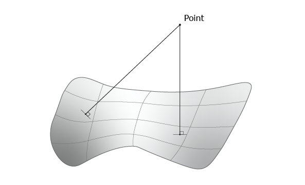
Note that the surface does not have to be of Geom_RectangularTrimmedSurface type. The algorithm will function with any class inheriting Geom_Surface.
GeomAPI_ProjectPointOnSurf is instantiated as in the following example:
To restrict the search for normals within the given rectangular domain [U1, U2, V1, V2], use the constructor GeomAPI_ProjectPointOnSurf Proj (P, S, U1, U2, V1, V2)
The values of U1, U2, V1 and V2 lie at or within their maximum and minimum limits, i.e.:
Having thus created the GeomAPI_ProjectPointOnSurf object, you can interrogate it.
The solutions are indexed in a range from 1 to Proj.NbPoints(). The point corresponding to the given index may be found:
For a given point corresponding to the given index:
The distance between the initial point and a point corresponding to the given index may be found:
This class offers a method, which returns the closest solution point to the starting point. This solution is accessed as follows:
Some operators have been redefined to help you find the nearest solution.
Standard_Real() returns the minimum distance from the point to the surface.
Standard_Integer() returns the number of solutions.
gp_Pnt2d() returns the nearest solution point.
Using these operators makes coding easier when you only need the nearest point. In this way,
can be written more concisely as:
In the second case, however, no intermediate GeomAPI_ProjectPointOnSurf object is created, and it is impossible to access other solution points.
If you want to use the wider range of functionalities available from the Extrema package, a call to the Extrema() method will return the algorithmic object for calculating the extrema as follows:
The To2d and To3d methods are used to;
These methods are called as follows:
The following standard topological objects can be created:
There are two root classes for their construction and modification:
BRepBuilderAPI_MakeVertex creates a new vertex from a 3D point from gp.
This class always creates a new vertex and has no other methods.
Use BRepBuilderAPI_MakeEdge to create from a curve and vertices. The basic method constructs an edge from a curve, two vertices, and two parameters.
where C is the domain of the edge; V1 is the first vertex oriented FORWARD; V2 is the second vertex oriented REVERSED; p1 and p2 are the parameters for the vertices V1 and V2 on the curve. The default tolerance is associated with this edge.
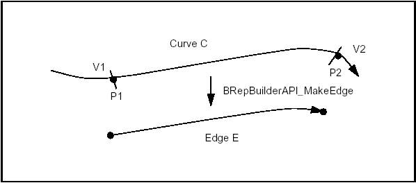
The following rules apply to the arguments:
The curve
The vertices
The parameters
The figure below illustrates two special cases, a semi-infinite edge and an edge on a periodic curve.
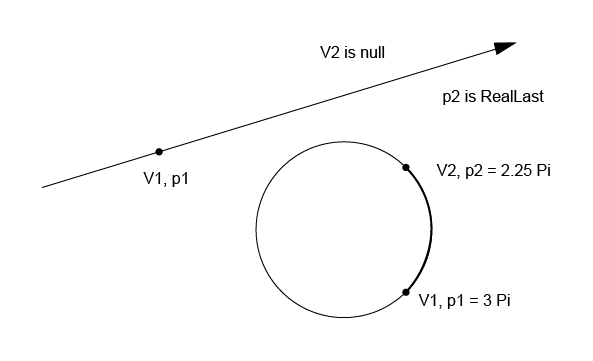
There exist supplementary edge construction methods derived from the basic one.
BRepBuilderAPI_MakeEdge class provides methods, which are all simplified calls of the previous one:
The five following methods are thus derived from the basic construction:
Six methods (the five above and the basic method) are also provided for curves from the gp package in place of Curve from Geom. The methods create the corresponding Curve from Geom and are implemented for the following classes:
gp_Lin creates a Geom_Line gp_Circ creates a Geom_Circle gp_Elips creates a Geom_Ellipse gp_Hypr creates a Geom_Hyperbola gp_Parab creates a Geom_Parabola
There are also two methods to construct edges from two vertices or two points. These methods assume that the curve is a line; the vertices or points must have different locations.
The class BRepBuilderAPI_MakeEdge can provide extra information and return an error status.
If BRepBuilderAPI_MakeEdge is used as a class, it can provide two vertices. This is useful when the vertices were not provided as arguments, for example when the edge was constructed from a curve and parameters. The two methods Vertex1 and Vertex2 return the vertices. Note that the returned vertices can be null if the edge is open in the corresponding direction.
The Error method returns a term of the BRepBuilderAPI_EdgeError enumeration. It can be used to analyze the error when IsDone method returns False. The terms are:
The following example creates a rectangle centered on the origin of dimensions H, L with fillets of radius R. The edges and the vertices are stored in the arrays theEdges and theVertices. We use class Array1OfShape (i.e. not arrays of edges or vertices). See the image below.
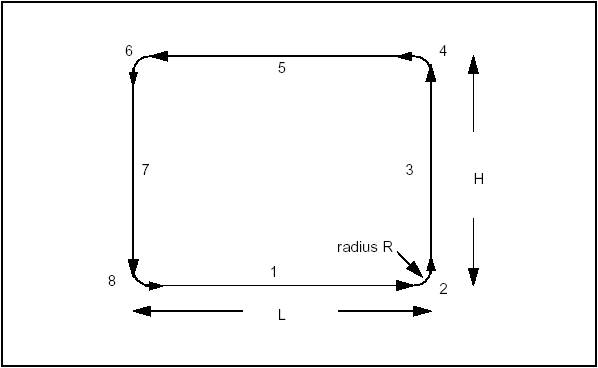
Use BRepBuilderAPI_MakeEdge2d class to make edges on a working plane from 2d curves. The working plane is a default value of the BRepBuilderAPI package (see the Plane methods).
BRepBuilderAPI_MakeEdge2d class is strictly similar to BRepBuilderAPI_MakeEdge, but it uses 2D geometry from gp and Geom2d instead of 3D geometry.
BRepBuilderAPI_MakePolygon class is used to build polygonal wires from vertices or points. Points are automatically changed to vertices as in BRepBuilderAPI_MakeEdge.
The basic usage of BRepBuilderAPI_MakePolygon is to create a wire by adding vertices or points using the Add method. At any moment, the current wire can be extracted. The close method can be used to close the current wire. In the following example, a closed wire is created from an array of points.
Short-cuts are provided for 2, 3, or 4 points or vertices. Those methods have a Boolean last argument to tell if the polygon is closed. The default value is False.
Two examples:
Example of a closed triangle from three vertices:
Example of an open polygon from four points:
BRepBuilderAPI_MakePolygon class maintains a current wire. The current wire can be extracted at any moment and the construction can proceed to a longer wire. After each point insertion, the class maintains the last created edge and vertex, which are returned by the methods Edge, FirstVertex and LastVertex.
When the added point or vertex has the same location as the previous one it is not added to the current wire but the most recently created edge becomes Null. The Added method can be used to test this condition. The MakePolygon class never raises an error. If no vertex has been added, the Wire is Null. If two vertices are at the same location, no edge is created.
Use BRepBuilderAPI_MakeFace class to create a face from a surface and wires. An underlying surface is constructed from a surface and optional parametric values. Wires can be added to the surface. A planar surface can be constructed from a wire. An error status can be returned after face construction.
A face can be constructed from a surface and four parameters to determine a limitation of the UV space. The parameters are optional, if they are omitted the natural bounds of the surface are used. Up to four edges and vertices are created with a wire. No edge is created when the parameter is infinite.
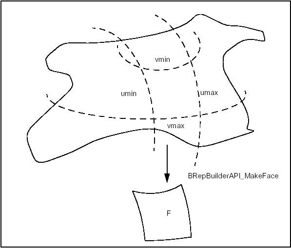
To make a face from the natural boundary of a surface, the parameters are not required:
Constraints on the parameters are similar to the constraints in BRepBuilderAPI_MakeEdge.
The two basic constructions (from a surface and from a surface and parameters) are implemented for all gp package surfaces, which are transformed in the corresponding Surface from Geom.
| gp package surface | Geom package surface | |
|---|---|---|
| gp_Pln | Geom_Plane | |
| gp_Cylinder | Geom_CylindricalSurface | |
| gp_Cone | creates a | Geom_ConicalSurface |
| gp_Sphere | Geom_SphericalSurface | |
| gp_Torus | Geom_ToroidalSurface |
Once a face has been created, a wire can be added using the Add method. For example, the following code creates a cylindrical surface and adds a wire.
More than one wire can be added to a face, provided that they do not cross each other and they define only one area on the surface. (Note that this is not checked).
For one wire, a simple syntax is provided to construct the face from the surface and the wire. The above lines could be written:
The edges on a face must have a parametric curve description. If there is no parametric curve for an edge of the wire on the face it is computed by projection, moreover, the calculation is possible only for the planar face.
A planar face can be created from only a wire, provided this wire defines a plane. For example, to create a planar face from a set of points you can use BRepBuilderAPI_MakePolygon and BRepBuilderAPI_MakeFace.
The last use of MakeFace is to copy an existing face to add new wires. For example, the following code adds a new wire to a face:
To add more than one wire an instance of the BRepBuilderAPI_MakeFace class can be created with the face and the first wire and the new wires inserted with the Add method.
The Error method returns an error status, which is a term from the BRepBuilderAPI_FaceError enumeration.
The wire is a composite shape built not from a geometry, but by the assembly of edges. BRepBuilderAPI_MakeWire class can build a wire from one or more edges or connect new edges to an existing wire.
Up to four edges can be used directly, for example:
For a higher or unknown number of edges the Add method must be used; for example, to build a wire from an array of shapes (to be edges).
The class can be constructed with a wire. A wire can also be added. In this case, all the edges of the wires are added. For example to merge two wires:
BRepBuilderAPI_MakeWire class connects the edges to the wire. When a new edge is added if one of its vertices is shared with the wire it is considered as connected to the wire. If there is no shared vertex, the algorithm searches for a vertex of the edge and a vertex of the wire, which are at the same location (the tolerances of the vertices are used to test if they have the same location). If such a pair of vertices is found, the edge is copied with the vertex of the wire in place of the original vertex. All the vertices of the edge can be exchanged for vertices from the wire. If no connection is found the wire is considered to be disconnected. This is an error.
BRepBuilderAPI_MakeWire class can return the last edge added to the wire (Edge method). This edge can be different from the original edge if it was copied.
The Error method returns a term of the BRepBuilderAPI_WireError enumeration: WireDone – no error occurred. EmptyWire – no initialization of the algorithm, an empty constructor was used. DisconnectedWire – the last added edge was not connected to the wire. NonManifoldWire – the wire with some singularity.
The shell is a composite shape built not from a geometry, but by the assembly of faces. Use BRepBuilderAPI_MakeShell class to build a Shell from a set of Faces. What may be important is that each face should have the required continuity. That is why an initial surface is broken up into faces.
The solid is a composite shape built not from a geometry, but by the assembly of shells. Use BRepBuilderAPI_MakeSolid class to build a Solid from a set of Shells. Its use is similar to the use of the MakeWire class: shells are added to the solid in the same way that edges are added to the wire in MakeWire.
The BRepPrimAPI package provides an API (Application Programming Interface) for construction of primitives such as:
It is possible to create partial solids, such as a sphere limited by longitude. In real models, primitives can be used for easy creation of specific sub-parts.
Sweeps are objects obtained by sweeping a profile along a path. The profile can be any topology and the path is usually a curve or a wire. The profile generates objects according to the following rules:
It is not allowed to sweep Solids and Composite Solids. Swept constructions along complex profiles such as BSpline curves also available in the BRepOffsetAPI package. This API provides simple, high level calls for the most common operations.
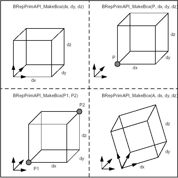
The class BRepPrimAPI_MakeBox allows building a parallelepiped box. The result is either a Shell or a Solid. There are four ways to build a box:
An error is raised if the box is flat in any dimension using the default precision. The following code shows how to create a box:
The four methods to build a box are shown in the figure:
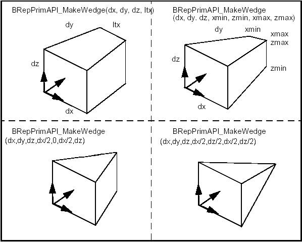
BRepPrimAPI_MakeWedge class allows building a wedge, which is a slanted box, i.e. a box with angles. The wedge is constructed in much the same way as a box i.e. from three dimensions dx,dy,dz plus arguments or from an axis system, three dimensions, and arguments.
The following figure shows two ways to build wedges. One is to add a dimension ltx, which is the length in x of the face at dy. The second is to add xmin, xmax, zmin and zmax to describe the face at dy.
The first method is a particular case of the second with xmin = 0, xmax = ltx, zmin = 0, zmax = dz. To make a centered pyramid you can use xmin = xmax = dx / 2, zmin = zmax = dz / 2.
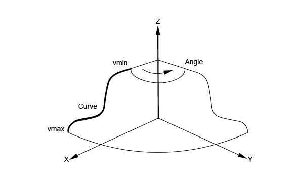
BRepPrimAPI_MakeOneAxis is a deferred class used as a root class for all classes constructing rotational primitives. Rotational primitives are created by rotating a curve around an axis. They cover the cylinder, the cone, the sphere, the torus, and the revolution, which provides all other curves.
The particular constructions of these primitives are described, but they all have some common arguments, which are:
The result of the OneAxis construction is a Solid, a Shell, or a Face. The face is the face covering the rotational surface. Remember that you will not use the OneAxis directly but one of the derived classes, which provide improved constructions. The following figure illustrates the OneAxis arguments.
BRepPrimAPI_MakeCylinder class allows creating cylindrical primitives. A cylinder is created either in the default coordinate system or in a given coordinate system gp_Ax2. There are two constructions:
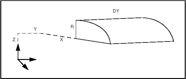
The following code builds the cylindrical face of the figure, which is a quarter of cylinder along the Y axis with the origin at X,Y,Z the length of DY and radius R.
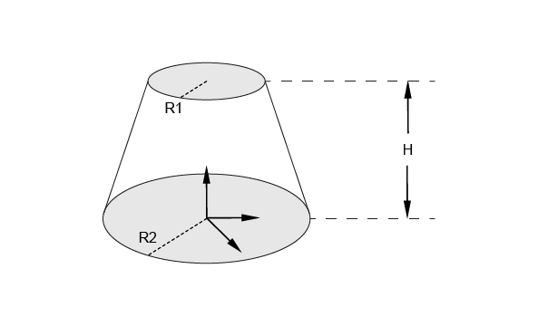
BRepPrimAPI_MakeCone class allows creating conical primitives. Like a cylinder, a cone is created either in the default coordinate system or in a given coordinate system (gp_Ax2). There are two constructions:
The following code builds the solid cone of the figure, which is located in the default system with radii R1 and R2 and height H.
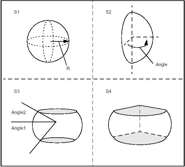
BRepPrimAPI_MakeSphere class allows creating spherical primitives. Like a cylinder, a sphere is created either in the default coordinate system or in a given coordinate system gp_Ax2. There are four constructions:
The following code builds four spheres from a radius and three angles.
Note that we could equally well choose to create Shells instead of Solids.
BRepPrimAPI_MakeTorus class allows creating toroidal primitives. Like the other primitives, a torus is created either in the default coordinate system or in a given coordinate system gp_Ax2. There are four constructions similar to the sphere constructions:
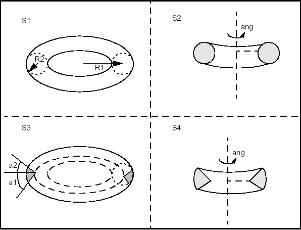
The following code builds four toroidal shells from two radii and three angles.
Note that we could equally well choose to create Solids instead of Shells.
BRepPrimAPI_MakeRevolution class allows building a uniaxial primitive from a curve. As other uniaxial primitives it can be created in the default coordinate system or in a given coordinate system.
The curve can be any Geom_Curve, provided it is planar and lies in the same plane as the Z-axis of local coordinate system. There are four modes of construction:
Sweeps are the objects you obtain by sweeping a profile along a path. The profile can be of any topology. The path is usually a curve or a wire. The profile generates objects according to the following rules:
It is forbidden to sweep Solids and Composite Solids. A Compound generates a Compound with the sweep of all its elements.
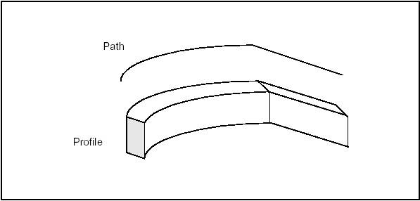
BRepPrimAPI_MakeSweep class is a deferred class used as a root of the following sweep classes:
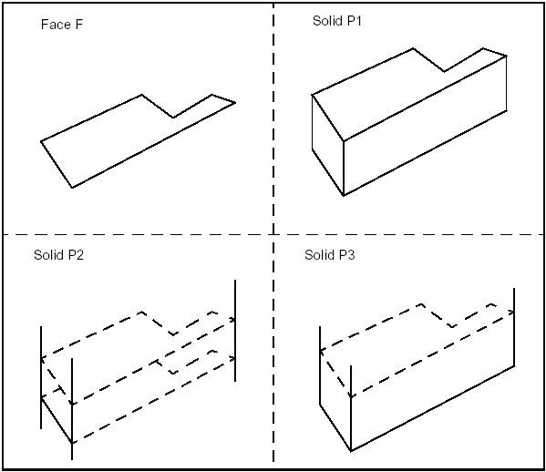
BRepPrimAPI_MakePrism class allows creating a linear prism from a shape and a vector or a direction.
The following code creates a finite, an infinite and a semi-infinite solid using a face, a direction and a length.
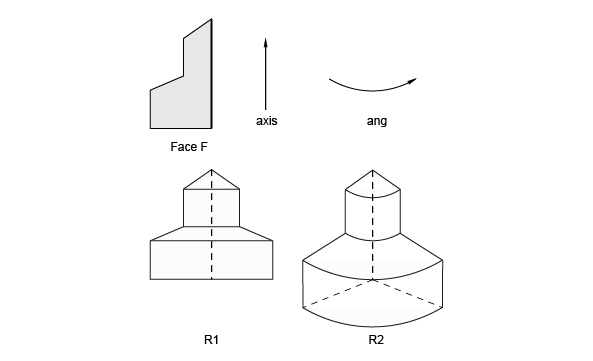
BRepPrimAPI_MakeRevol class allows creating a rotational sweep from a shape, an axis (gp_Ax1), and an angle. The angle has a default value of 2*PI which means a closed revolution.
BRepPrimAPI_MakeRevol constructors have a last argument to copy or share the original shape. The following code creates a full and a partial rotation using a face, an axis and an angle.
Boolean operations are used to create new shapes from the combinations of two groups of shapes.
| Operation | Result |
|---|---|
| Fuse | all points in S1 or S2 |
| Common | all points in S1 and S2 |
| Cut S1 by S2 | all points in S1 and not in S2 |
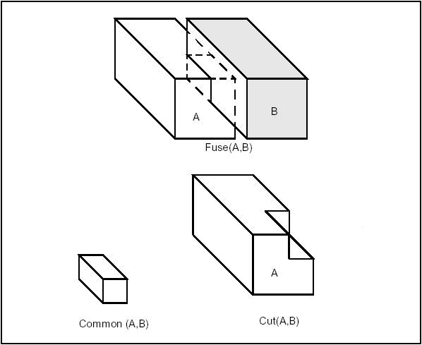
From the viewpoint of Topology these are topological operations followed by blending (putting fillets onto edges created after the topological operation).
Topological operations are the most convenient way to create real industrial parts. As most industrial parts consist of several simple elements such as gear wheels, arms, holes, ribs, tubes and pipes. It is usually easy to create those elements separately and then to combine them by Boolean operations in the whole final part.
See Boolean Operations for detailed documentation.
Boolean Operations have the following types of the arguments and produce the following results:
BRepAlgoAPI_BooleanOperation class is the deferred root class for Boolean operations.
BRepAlgoAPI_Fuse performs the Fuse operation.
BRepAlgoAPI_Common performs the Common operation.
BRepAlgoAPI_Cut performs the Cut operation.
BRepAlgoAPI_Section performs the section, described as a TopoDS_Compound made of TopoDS_Edge.
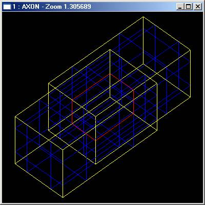
Open CASCADE Technology topological tools provide algorithms to
It is possible to create the planar faces from the arbitrary set of planar edges randomly located in 3D space. This feature might be useful if you need for instance to restore the shape from the wireframe model:
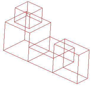
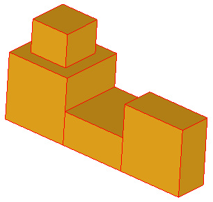
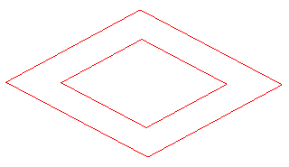
To make the faces from edges it is, firstly, necessary to create planar wires from the given edges and than create planar faces from each wire. The static methods BOPAlgo_Tools::EdgesToWires and BOPAlgo_Tools::WiresToFaces can be used for that:
These methods can also be used separately:
The following methods allow classifying the different shapes relatively other shapes:
The following methods allow reorienting shapes in the containers:
The following methods allow creating new shapes from the existing ones:
The following methods allow building PCurves of edges on faces:
The following methods allow checking the validity of the shapes:
The following methods allow taking a point located inside the face:
The following methods allow getting the normal direction for the face/surface:
The Topology API of Open CASCADE Technology (OCCT) includes the following six packages:
The classes provided by the API have the following features:
Let us use the class BRepBuilderAPI_MakeEdge to create a linear edge from two points.
This is the simplest way to create edge E from two points P1, P2, but the developer can test for errors when he is not as confident of the data as in the previous example.
In this example an intermediary object ME has been introduced. This can be tested for the completion of the function before accessing the result. More information on error handling in the topology programming interface can be found in the next section.
BRepBuilderAPI_MakeEdge provides valuable information. For example, when creating an edge from two points, two vertices have to be created from the points. Sometimes you may be interested in getting these vertices quickly without exploring the new edge. Such information can be provided when using a class. The following example shows a function creating an edge and two vertices from two points.
The class BRepBuilderAPI_MakeEdge provides two methods Vertex1 and Vertex2, which return two vertices used to create the edge.
How can BRepBuilderAPI_MakeEdge be both a function and a class? It can do this because it uses the casting capabilities of C++. The BRepBuilderAPI_MakeEdge class has a method called Edge; in the previous example the line E = ME could have been written.
This instruction tells the C++ compiler that there is an implicit casting of a BRepBuilderAPI_MakeEdge into a TopoDS_Edge using the Edge method. It means this method is automatically called when a BRepBuilderAPI_MakeEdge is found where a TopoDS_Edge is required.
This feature allows you to provide classes, which have the simplicity of function calls when required and the power of classes when advanced processing is necessary. All the benefits of this approach are explained when describing the topology programming interface classes.
All topological API algorithms support the history of shape modifications (or just History) for their arguments. Generally, the history is available for the following types of sub-shapes of input shapes:
Some algorithms also support the history for Solids.
The history information consists of the following information:
The History is filled basing on the result of the operation. History cannot return any shapes not contained in the result. If the result of the operation is an empty shape, all input shapes will be considered as Deleted and none will have Modified and Generated shapes.
The history information can be accessed by the API methods:
The shape is considered as Deleted during the operation if all of the following conditions are met:
For example, in the CUT operation between two intersecting solids all vertices/edges/faces located completely inside the Tool solid will be Deleted during the operation.
The shape is considered as Modified during the operation if the result shape contains the splits of the shape, not the shape itself. The shape can be modified only into the shapes with the same dimension. The splits of the shape contained in the result shape are Modified from the shape. The Modified shapes are created from the sub-shapes of the input shapes and, generally, repeat their geometry.
The list of Modified elements will contain only those contributing to the result of the operation. If the list is empty, the shape has not been modified and it is necessary to check if it has been Deleted.
For example, after translation of the shape in any direction all its sub-shapes will be modified into their translated copies.
The shapes contained in the result shape are considered as Generated from the input shape if they were produced during the operation and have a different dimension from the shapes from which they were created.
The list of Generated elements will contain only those included in the result of the operation. If the list is empty, no new shapes have been Generated from the shape.
For example, extrusion of the edge in some direction will create a face. This face will be generated from the edge.
BRepTools_History is the general History tool intended for unification of the histories of different algorithms.
BRepTools_History can be created from any algorithm supporting the standard history methods *(IsDeleted(), Modified()* and Generated()):
BRepTools_History also allows merging histories. Thus, if you have two or more subsequent operations you can get one final history combined from histories of these operations:
It is possible to merge the second history into the first one:
Or create the new history keeping the two histories unmodified:
The possibilities of Merging histories and history creation from the API algorithms allow providing easy History support for the new algorithms.
DRAW History support for the algorithms is provided by three basic commands:
For more information on the Draw History mechanism, refer to the corresponding chapter in the Draw users guide - History commands.
This library provides algorithms to make fillets and chamfers on shape edges. The following cases are addressed:
If there is a concavity, both surfaces that need to be extended and those, which do not, are processed.
A fillet is a smooth face replacing a sharp edge.
BRepFilletAPI_MakeFillet class allows filleting a shape.
To produce a fillet, it is necessary to define the filleted shape at the construction of the class and add fillet descriptions using the Add method.
A fillet description contains an edge and a radius. The edge must be shared by two faces. The fillet is automatically extended to all edges in a smooth continuity with the original edge. It is not an error to add a fillet twice, the last description holds.
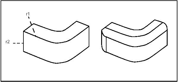
In the following example a filleted box with dimensions a,b,c and radius r is created.
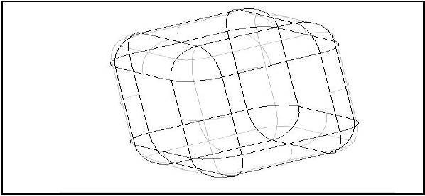
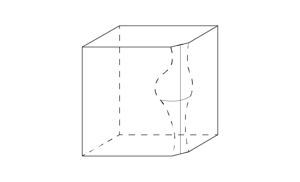
A chamfer is a rectilinear edge replacing a sharp vertex of the face.
The use of BRepFilletAPI_MakeChamfer class is similar to the use of BRepFilletAPI_MakeFillet, except for the following:
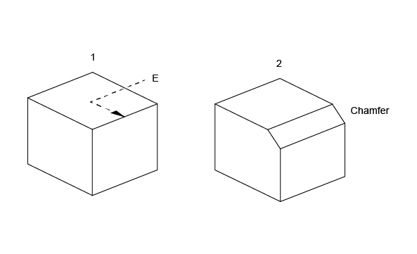
BRepFilletAPI_MakeFillet2d class allows constructing fillets and chamfers on planar faces. To create a fillet on planar face: define it, indicate, which vertex is to be deleted, and give the fillet radius with AddFillet method.
A chamfer can be calculated with AddChamfer method. It can be described by
If face F2 is created by 2D fillet and chamfer builder from face F1, the builder can be rebuilt (the builder recovers the status it had before deletion). To do so, use the following Syntax:
These classes provide the following services:
Offset computation can be performed using BRepOffsetAPI_MakeOffsetShape. This class provides API to the two different offset algorithms:
Offset algorithm based on computation of the analytical continuation. Meaning of the parameters can be found in BRepOffsetAPI_MakeOffsetShape::PerformByJoin method description. The list below demonstrates principal scheme of this algorithm:
The second algorithm is based on the fact that the offset computation for a single face without continuation can always be built. The list below shows simple offset algorithm:
The snippets below show usage examples:
Shelling is used to offset given faces of a solid by a specific value. It rounds or intersects adjacent faces along its edges depending on the convexity of the edge. The MakeThickSolidByJoin method of the BRepOffsetAPI_MakeThickSolid takes the solid, the list of faces to remove and an offset value as input.
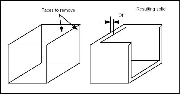
Also it is possible to create solid between shell, offset shell. This functionality can be called using BRepOffsetAPI_MakeThickSolid::MakeThickSolidBySimple method. The code below shows usage example:
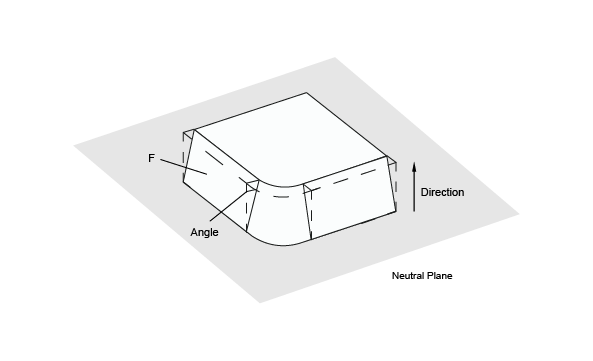
BRepOffsetAPI_DraftAngle class allows modifying a shape by applying draft angles to its planar, cylindrical and conical faces.
The class is created or initialized from a shape, then faces to be modified are added; for each face, three arguments are used:
The following code places a draft angle on several faces of a shape; the same direction, angle and neutral plane are used for each face:
BRepOffsetAPI_MakePipe class allows creating a pipe from a Spine, which is a Wire and a Profile which is a Shape. This implementation is limited to spines with smooth transitions, sharp transitions are precessed by BRepOffsetAPI_MakePipeShell. To be more precise the continuity must be G1, which means that the tangent must have the same direction, though not necessarily the same magnitude, at neighboring edges.
The angle between the spine and the profile is preserved throughout the pipe.
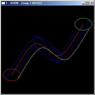
BRepOffsetAPI_MakeEvolved class allows creating an evolved solid from a Spine (planar face or wire) and a profile (wire).
The evolved solid is an unlooped sweep generated by the spine and the profile.
The evolved solid is created by sweeping the profile’s reference axes on the spine. The origin of the axes moves to the spine, the X axis and the local tangent coincide and the Z axis is normal to the face.
The reference axes of the profile can be defined following two distinct modes:
BRepBuilderAPI_Transform class can be used to apply a transformation to a shape (see class gp_Trsf). The methods have a boolean argument to copy or share the original shape, as long as the transformation allows (it is only possible for direct isometric transformations). By default, the original shape is shared.
The following example deals with the rotation of shapes.
Use the BRepBuilderAPI_Copy class to duplicate a shape. A new shape is thus created. In the following example, a solid is copied:
A method can report an error in the two following situations:
The second situation is supposed to become increasingly exceptional as a system is debugged and it is handled by the exception mechanism. Using exceptions avoids handling error statuses in the call to a method: a very cumbersome style of programming.
In the first situation, an exception is also supposed to be raised because the calling method should have verified the arguments and if it did not do so, there is a bug. For example, if before calling MakeEdge you are not sure that the two points are non-identical, this situation must be tested.
Making those validity checks on the arguments can be tedious to program and frustrating as you have probably correctly surmised that the method will perform the test twice. It does not trust you. As the test involves a great deal of computation, performing it twice is also time-consuming.
Consequently, you might be tempted to adopt the highly inadvisable style of programming illustrated in the following example:
To help the user, the Topology API classes only raise the exception StdFail_NotDone. Any other exception means that something happened which was unforeseen in the design of this API.
The NotDone exception is only raised when the user tries to access the result of the computation and the original data is corrupted. At the construction of the class instance, if the algorithm cannot be completed, the internal flag NotDone is set. This flag can be tested and in some situations a more complete description of the error can be queried. If the user ignores the NotDone status and tries to access the result, an exception is raised.
Sewing allows creation of connected topology (shells and wires) from a set of separate topological elements (faces and edges). For example, Sewing can be used to create of shell from a compound of separate faces.
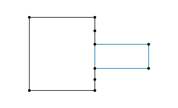
It is important to distinguish between sewing and other procedures, which modify the geometry, such as filling holes or gaps, gluing, bending curves and surfaces, etc.
Sewing does not change geometrical representation of the shapes. Sewing applies to topological elements (faces, edges) which are not connected but can be connected because they are geometrically coincident : it adds the information about topological connectivity. Already connected elements are left untouched in case of manifold sewing.
Let us define several terms:
The sewing algorithm is one of the basic algorithms used for shape processing, therefore its quality is very important.
Sewing algorithm is implemented in the class BRepBuilder_Sewing. This class provides the following methods:
Sewing supports working mode with big value tolerance. It is not necessary to repeat sewing step by step while smoothly increasing tolerance.
It is also possible to sew edges to wire and to sew locally separate faces and edges from a shape.
The Sewing algorithm can be subdivided into several independent stages, some of which can be turned on or off using Boolean or other flags.
In brief, the algorithm should find a set of merge candidates for each free boundary, filter them according to certain criteria, and finally merge the found candidates and build the resulting sewn shape.
Each stage of the algorithm or the whole algorithm can be adjusted with the following parameters:
To connect a set of n contiguous but independent faces, do the following:
If all faces have been sewn correctly, the result is a shell. Otherwise, it is a compound. After a successful sewing operation all faces have a coherent orientation.
To produce a closed shell, Sewing allows specifying the value of working tolerance, exceeding the size of small faces belonging to the shape.
However, if we produce an open shell, it is possible to get incorrect sewing results if the value of working tolerance is too large (i.e. it exceeds the size of faces lying on an open boundary).
The following recommendations can be proposed for tuning-up the sewing process:
To create one or several shells from a set of faces, sewing merges edges, which belong to different faces or one closed face.
Face sewing supports manifold and non manifold modes. Manifold mode can produce only a manifold shell. Sewing should be used in the non manifold mode to create non manifold shells.
Manifold sewing of faces merges only two nearest edges belonging to different faces or one closed face with each other. Non manifold sewing of faces merges all edges at a distance less than the specified tolerance.
For a complex topology it is advisable to apply first the manifold sewing and then the non manifold sewing a minimum possible working tolerance. However, this is not necessary for a easy topology.
Giving a large tolerance value to non manifold sewing will cause a lot of incorrectness since all nearby geometry will be sewn.
If a shape still has some non-sewn faces or edges after sewing, it is possible to use local sewing with a greater tolerance.
Local sewing is especially good for open shells. It allows sewing an unwanted hole in one part of the shape and keeping a required hole, which is smaller than the working tolerance specified for the local sewing in the other part of the shape. Local sewing is much faster than sewing on the whole shape.
All preexisting connections of the whole shape are kept after local sewing.
For example, if you want to sew two open shells having coincided free edges using local sewing, it is necessary to create a compound from two shells then load the full compound using method BRepBuilderAPI_Sewing::Load(). After that it is necessary to add local sub-shapes, which should be sewn using method BRepBuilderAPI_Sewing::Add(). The result of sewing can be obtained using method BRepBuilderAPI_Sewing::SewedShape().
See the example:
This library contained in BRepFeat package is necessary for creation and manipulation of form and mechanical features that go beyond the classical boundary representation of shapes. In that sense, BRepFeat is an extension of BRepBuilderAPI package.
The form features are depressions or protrusions including the following types:
Depending on whether you wish to make a depression or a protrusion, you can choose either to remove matter (Boolean cut: Fuse equal to 0) or to add it (Boolean fusion: Fuse equal to 1).
The semantics of form feature creation is based on the construction of shapes:
The shape defining the construction of a feature can be either a supporting edge or a concerned area of a face.
In case of supporting edge, this contour can be attached to a face of the basis shape by binding. When the contour is bound to this face, the information that the contour will slide on the face becomes available to the relevant class methods. In case of the concerned area of a face, you can, for example, cut it out and move it at a different height, which defines the limiting face of a protrusion or depression.
Topological definition with local operations of this sort makes calculations simpler and faster than a global operation. The latter would entail a second phase of removing unwanted matter to get the same result.
The Form from BRepFeat package is a deferred class used as a root for form features. It inherits MakeShape from BRepBuilderAPI and provides implementation of methods keep track of all sub-shapes.
Prism
The class BRepFeat_MakePrism is used to build a prism interacting with a shape. It is created or initialized from
There are six Perform methods:
| Method | Description |
|---|---|
| Perform(Height) | The resulting prism is of the given length. |
| Perform(Until) | The prism is defined between the position of the base and the given face. |
| Perform(From, Until) | The prism is defined between the two faces From and Until. |
| PerformUntilEnd() | The prism is semi-infinite, limited by the actual position of the base. |
| PerformFromEnd(Until) | The prism is semi-infinite, limited by the face Until. |
| PerformThruAll() | The prism is infinite. In the case of a depression, the result is similar to a cut with an infinite prism. In the case of a protrusion, infinite parts are not kept in the result. |
Note that Add method can be used before Perform methods to indicate that a face generated by an edge slides onto a face of the base shape.
In the following sequence, a protrusion is performed, i.e. a face of the shape is changed into a prism.
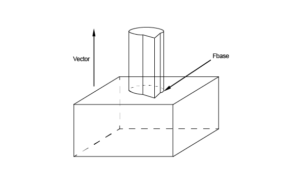
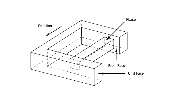
Draft Prism
The class BRepFeat_MakeDPrism is used to build draft prism topologies interacting with a basis shape. These can be depressions or protrusions. A class object is created or initialized from:
Evidently the input data for MakeDPrism are the same as for MakePrism except for a new parameter Angle and a missing parameter Direction: the direction of the prism generation is determined automatically as the normal to the base of the prism. The semantics of draft prism feature creation is based on the construction of shapes:
The shape defining construction of the draft prism feature can be either the supporting edge or the concerned area of a face.
In case of the supporting edge, this contour can be attached to a face of the basis shape by binding. When the contour is bound to this face, the information that the contour will slide on the face becomes available to the relevant class methods. In case of the concerned area of a face, it is possible to cut it out and move it to a different height, which will define the limiting face of a protrusion or depression direction .
The Perform methods are the same as for MakePrism.
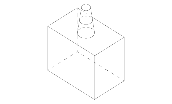
Revolution
The class BRepFeat_MakeRevol is used to build a revolution interacting with a shape. It is created or initialized from:
There are four Perform methods:
| Method | Description |
|---|---|
| Perform(Angle) | The resulting revolution is of the given magnitude. |
| Perform(Until) | The revolution is defined between the actual position of the base and the given face. |
| Perform(From, Until) | The revolution is defined between the two faces, From and Until. |
| PerformThruAll() | The result is similar to Perform(2*PI). |
Note that Add method can be used before Perform methods to indicate that a face generated by an edge slides onto a face of the base shape.
In the following sequence, a face is revolved and the revolution is limited by a face of the base shape.
Pipe
The class BRepFeat_MakePipe constructs compound shapes with pipe features: depressions or protrusions. A class object is created or initialized from:
There are three Perform methods:
| Method | Description |
|---|---|
| Perform() | The pipe is defined along the entire path (spine wire) |
| Perform(Until) | The pipe is defined along the path until a given face |
| Perform(From, Until) | The pipe is defined between the two faces From and Until |
Let us have a look at the example:
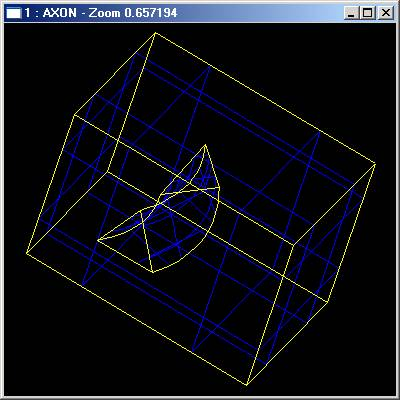
Mechanical features include ribs, protrusions and grooves (or slots), depressions along planar (linear) surfaces or revolution surfaces.
The semantics of mechanical features is built around giving thickness to a contour. This thickness can either be symmetrical – on one side of the contour – or dissymmetrical – on both sides. As in the semantics of form features, the thickness is defined by construction of shapes in specific contexts.
The development contexts differ, however, in the case of mechanical features. Here they include extrusion:
A class object is created or initialized from
Linear Form
Linear form is implemented in MakeLinearForm class, which creates a rib or a groove along a planar surface. There is one Perform() method, which performs a prism from the wire along the direction1 and direction2 interacting with base shape Sbase. The height of the prism is Magnitude(Direction1)+Magnitude(direction2).
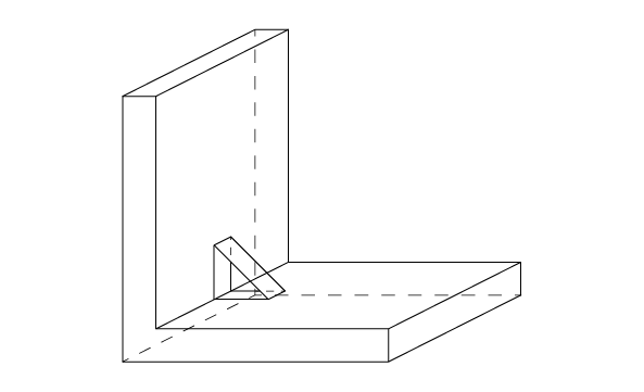
Gluer
The class BRepFeat_Gluer allows gluing two solids along faces. The contact faces of the glued shape must not have parts outside the contact faces of the basic shape. Upon completion the algorithm gives the glued shape with cut out parts of faces inside the shape.
The class is created or initialized from two shapes: the “glued” shape and the basic shape (on which the other shape is glued). Two Bind methods are used to bind a face of the glued shape to a face of the basic shape and an edge of the glued shape to an edge of the basic shape.
Note that every face and edge has to be bounded, if two edges of two glued faces are coincident they must be explicitly bounded.
The class BRepFeat_SplitShape is used to split faces of a shape into wires or edges. The shape containing the new entities is rebuilt, sharing the unmodified ones.
The class is created or initialized from a shape (the basic shape). Three Add methods are available:
Note The added wires and edges must define closed wires on faces or wires located between two existing edges. Existing edges must not be intersected.
The Open CASCADE Technology Defeaturing algorithm is intended for removal of the unwanted parts or features from the model. These parts can be holes, protrusions, gaps, chamfers, fillets, etc.
Feature detection is not performed, and all features to be removed should be defined by the user. The input shape is not modified during Defeaturing, the new shape is built in the result.
On the API level the Defeaturing algorithm is implemented in the BRepAlgoAPI_Defeaturing class. At input the algorithm accepts the shape to remove the features from and the features (one or many) to be removed from the shape. Currently, the input shape should be either SOLID, or COMPSOLID, or COMPOUND of SOLIDs. The features to be removed are defined by the sets of faces forming them. It does not matter how the feature faces are given: as separate faces or their collections. The faces should belong to the initial shape, else they are ignored.
The actual features removal is performed by the low-level BOPAlgo_RemoveFeatures algorithm. On the API level, all inputs are passed into the tool and the method BOPAlgo_RemoveFeatures::Perform() is called.
Before removing features, all faces to be removed from the shape are sorted into connected blocks - each block represents a single feature to be removed. The features are removed from the shape one by one, which allows removing all possible features even if there are some problems with their removal (e.g. due to incorrect input data).
The removed feature is filled by the extension of the faces adjacent to it. In general, the algorithm removing a single feature from the shape goes as follows:
If the single feature removal was successful, the result shape is overwritten with the new shape, otherwise the results are not kept, and the warning is given. Either way the process continues with the next feature.
The Defeaturing algorithm has the following options:
and the options available from base class (BOPAlgo_Options):
Note that the other options of the base class are not supported here and will have no effect.
History support allows tracking modification of the input shape in terms of Modified, IsDeleted and Generated. By default, the history is collected, but it is possible to disable it using the method SetToFillHistory(false). On the low-level the history information is collected by the history tool BRepTools_History, which can be accessed through the method BOPAlgo_RemoveFeatures::History().
Error/Warning reporting system allows obtaining the extended overview of the Errors/Warnings occurred during the operation. As soon as any error appears, the algorithm stops working. The warnings allow continuing the job and informing the user that something went wrong. The algorithm returns the following errors/warnings:
For more information on the error/warning reporting system, see the chapter Errors and warnings reporting system of Boolean operations user guide.
Parallel processing mode - allows running the algorithm in parallel mode obtaining the result faster.
The algorithm has certain limitations:
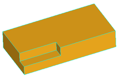
Note, that for successful removal of the feature, the extended faces adjacent to the feature should cover the feature completely, otherwise the solids will not be rebuild. Take a look at the simple shape on the image below:
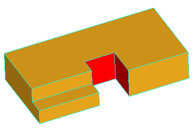
Removal of all three faces of the gap is not going to work, because there will be no face to fill the transverse part of the step. Although, removal of only two faces, keeping one of the transverse faces, will fill the gap with the kept face:
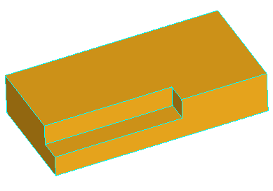
Here is the example of usage of the BRepAlgoAPI_Defeaturing algorithm on the C++ level:
Use the API history methods to track the history of a shape:
The command removefeatures allows using the Defeaturing algorithm on the Draw level.
The standard history commands can be used to track the history of shape modification during Defeaturing.
For more details on commands above, refer to the Defeaturing commands of the Draw test harness user guide.
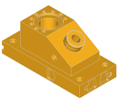
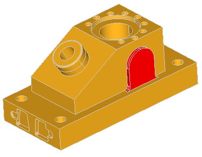
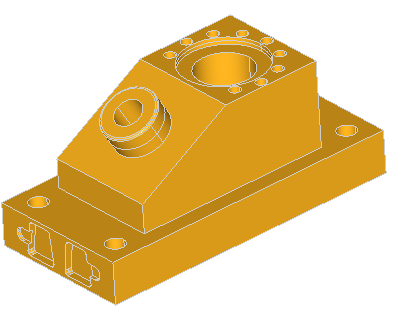
Here are the examples of defeaturing of the ANC101 model:

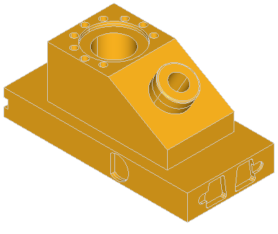
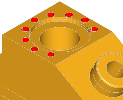
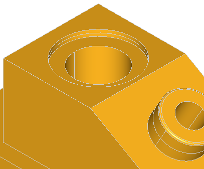
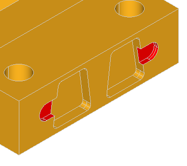
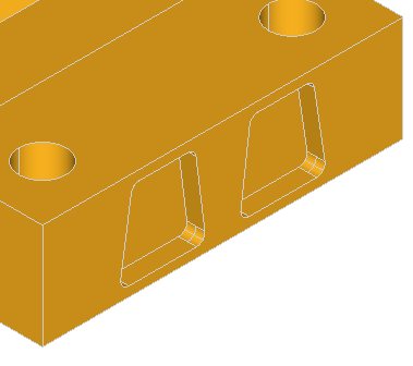
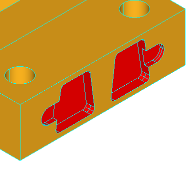
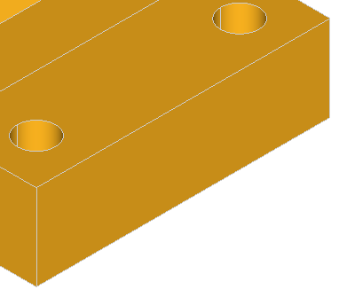

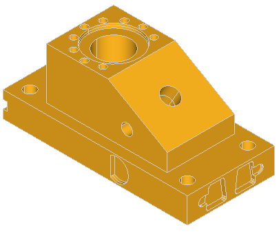
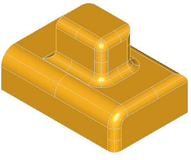
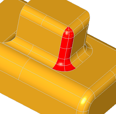
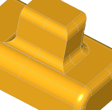
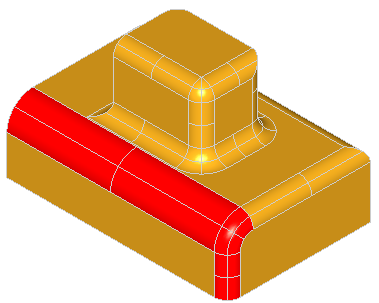
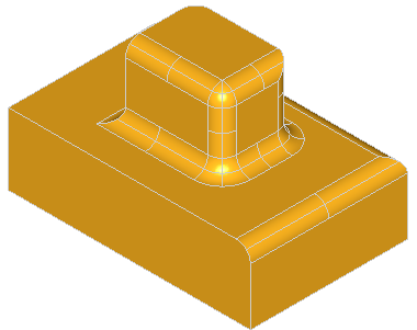
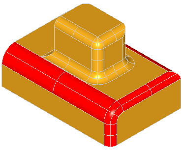
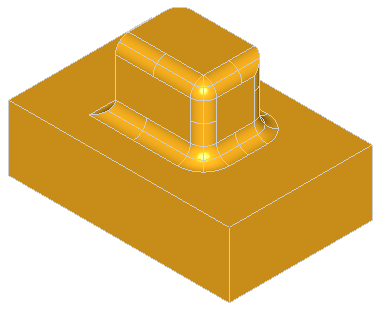
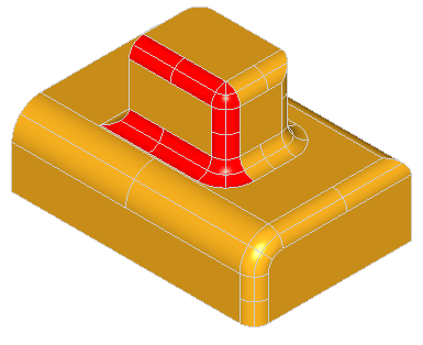
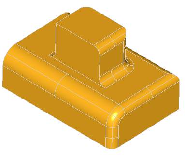
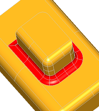
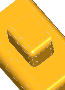
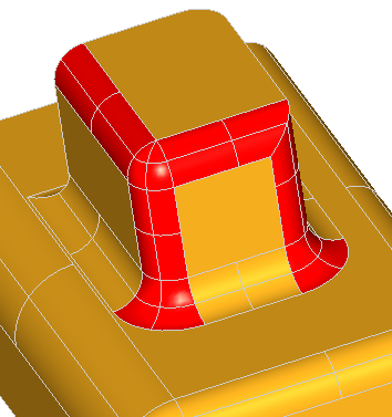
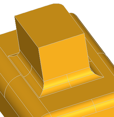
Here are the few examples of defeaturing of the model containing boxes with blends:
Open CASCADE Technology provides tools for making an arbitrary 3D model (or just shape) periodic in 3D space in the specified directions.
Periodicity of the shape means that the shape can be repeated in any periodic direction any number of times without creation of the new geometry or splits. The idea of this algorithm is to make the shape look similarly on the opposite sides or on the period bounds of periodic directions. It does not mean that the opposite sides of the shape will be mirrored. It just means that the opposite sides of the shape should be split by each other and obtain the same geometry on opposite sides. Such approach will allow repeating the shape, i.e. translating the copy of a shape on the period, without creation of new geometry because there will be no coinciding parts of different dimension.
For better understanding of what periodicity means lets create a simple prism and make it periodic. The following draw script creates the L-shape prism with extensions 10x5x10:
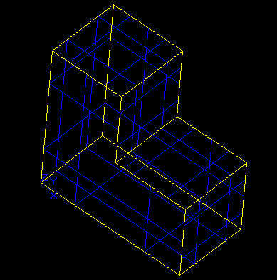
Making this shape periodic in X, Y and Z directions with the periods matching the shape's extensions should make the splits of negative X and Z sides of the shape. The shape is already similar on opposite sides of Y directions, thus no new splits is expected. Here is the shape after making it periodic:
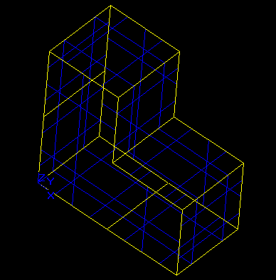
And here is the repetition of the shape once in X and Z directions:
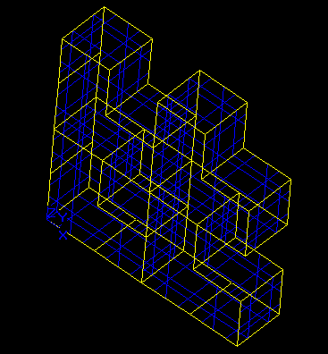
The OCCT Shape Periodicity tools also allows making the shape periodic with the period not matching the shape's extensions. Let's make the shape periodic with 11, 6 and 11 for X, Y, Z periods accordingly. Such values of periods mean that there will be a gap between repeated shapes, and since during repetition the opposite sides do not touch the shape will not be split at all. Here is the repetition of the shape once in X and Z directions:
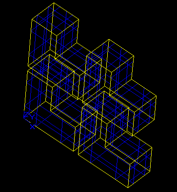
As expected, the shape is not split and the repeated elements do not touch.
If necessary the algorithm will trim the shape to fit into the requested period by splitting it with the planes limiting the shape's requested periods. E.g. let's make the L-shape periodic only in X direction with the period 2 starting at X parameter 4:
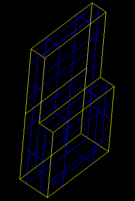
For making the shape periodic in certain direction the algorithm performs the following steps:
Repeated copying of the geometry ensures that the corner edges of the periodic shape will have the same geometry on opposite sides of all periodic directions.
Thus, in the periodic shape the geometry from positive side of the shape is always copied on the negative side of periodic directions.
The algorithm also associates the identical (or twin) shapes located on the opposite sides of the periodic shape. By the construction, the twin shapes should always have the same geometry and distanced from each other on the period. It is possible that the shape does not have any twins. It means that when repeating this shape will not touch the opposite side of the shape. In the example when the periods of the shape are grater than its extensions, non of the sub-shapes has a twin.
The algorithm also provides the methods to repeat the periodic shape in periodic directions. To repeat shape the algorithm makes the requested number of copies of the shape and translates them one by one on the time * period value. After all copies are made and translated they are glued to have valid shape. The subsequent repetitions are performed on the repeated shape, thus e.g. repeating the shape two times in any periodic direction will create result containing three shapes (original plus two copies). Single subsequent repetition in any direction will result already in 6 shapes.
The repetitions can be cleared and started over.
The algorithm supports the history of shapes modifications, thus it is possible to track how the shapes have been changed to make it periodic and what new shapes have been created during repetitions. Both split history and history of periodic shape repetition are available here. Note, that all repeated shapes are stored as generated into the history.
BRepTools_History is used for history support.
The algorithm supports the Error/Warning reporting system which allows obtaining the extended overview of the errors and warning occurred during the operation. As soon as any error appears the algorithm stops working. The warnings allow continuing the job, informing the user that something went wrong. The algorithm returns the following alerts:
For more information on the error/warning reporting system please see the chapter Errors and warnings reporting system of Boolean operations user guide.
The algorithm is implemented in the class BOPAlgo_MakePeriodic. Here is the example of its usage on the API level:
Please note, that the class is based on the options class BOPAlgo_Options, which provides the following options for the algorithm:
All the history information obtained during the operation is stored into BRepTools_History object and available through History() method:
For the usage of the MakePeriodic algorithm on the Draw level the following commands have been implemented:
For more details on the periodicity commands please refer the Periodicity commands of the Draw test harness user guide.
To track the history of a shape modification during MakePeriodic operation the standard history commands can be used.
To have possibility to access the error/warning shapes of the operation use the bdrawwarnshapes command before running the algorithm (see command usage in the Errors and warnings reporting system of Boolean operations user guide).
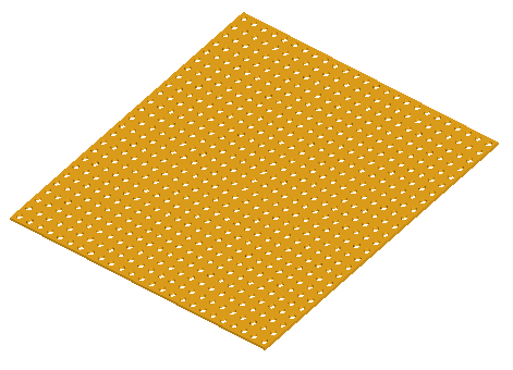
Imagine that you need to make the drills in the plate on the same distance from each other. To model this process it is necessary to make a lot of cylinders (simulating the drills) and cut these cylinders from the plate. With the periodicity tool, the process looks very simple:
To provide the precision required in industrial design, drawings need to offer the possibility of removing lines, which are hidden in a given projection.
For this the Hidden Line Removal component provides two algorithms: HLRBRep_Algo and HLRBRep_PolyAlgo.
These algorithms are based on the principle of comparing each edge of the shape to be visualized with each of its faces, and calculating the visible and the hidden parts of each edge. Note that these are not the algorithms used in generating shading, which calculate the visible and hidden parts of each face in a shape to be visualized by comparing each face in the shape with every other face in the same shape. These algorithms operate on a shape and remove or indicate edges hidden by faces. For a given projection, they calculate a set of lines characteristic of the object being represented. They are also used in conjunction with extraction utilities, which reconstruct a new, simplified shape from a selection of the results of the calculation. This new shape is made up of edges, which represent the shape visualized in the projection.
HLRBRep_Algo allows working with the shape itself, whereas HLRBRep_PolyAlgo works with a polyhedral simplification of the shape. When you use HLRBRep_Algo, you obtain an exact result, whereas, when you use HLRBRep_PolyAlgo, you reduce the computation time, but obtain polygonal segments.
No smoothing algorithm is provided. Consequently, a polyhedron will be treated as such and the algorithms will give the results in form of line segments conforming to the mathematical definition of the polyhedron. This is always the case with HLRBRep_PolyAlgo.
HLRBRep_Algo and HLRBRep_PolyAlgo can deal with any kind of object, for example, assemblies of volumes, surfaces, and lines, as long as there are no unfinished objects or points within it.
However, there some restrictions in HLR use:
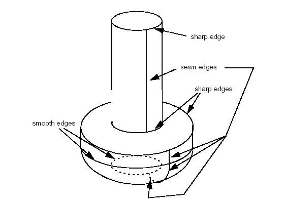
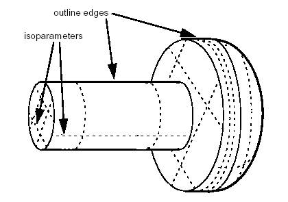
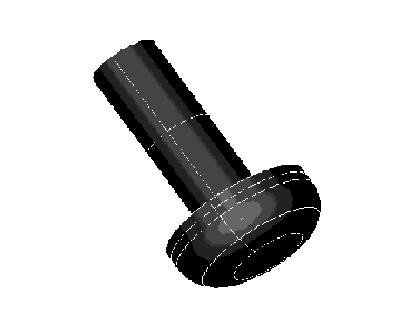
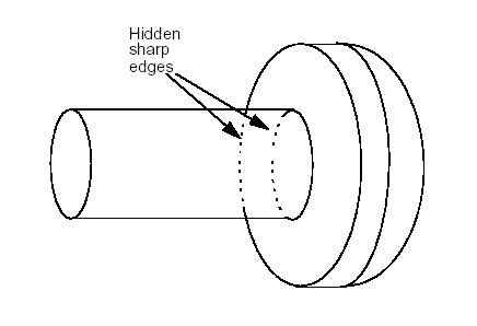
The following services are related to Hidden Lines Removal :
To pass a TopoDS_Shape to an HLRBRep_Algo object, use HLRBRep_Algo::Add. With an HLRBRep_PolyAlgo object, use HLRBRep_PolyAlgo::Load. If you wish to add several shapes, use Add or Load as often as necessary.
HLRBRep_Algo::Projector and HLRBRep_PolyAlgo::Projector set a projector object which defines the parameters of the view. This object is an HLRAlgo_Projector.
HLRBRep_PolyAlgo::Update launches the calculation of outlines of the shape visualized by the HLRBRep_PolyAlgo framework.
In the case of HLRBRep_Algo, use HLRBRep_Algo::Update. With this algorithm, you must also call the method HLRBRep_Algo::Hide to calculate visible and hidden lines of the shape to be visualized. With an HLRBRep_PolyAlgo object, visible and hidden lines are computed by HLRBRep_PolyHLRToShape.
The classes HLRBRep_HLRToShape and HLRBRep_PolyHLRToShape present a range of extraction filters for an HLRBRep_Algo object and an HLRBRep_PolyAlgo object, respectively. They highlight the type of edge from the results calculated by the algorithm on a shape. With both extraction classes, you can highlight the following types of output:
To perform extraction on an HLRBRep_PolyHLRToShape object, use HLRBRep_PolyHLRToShape::Update function.
For an HLRBRep_HLRToShape object built from an HLRBRepAlgo object you can also highlight:
Open CASCADE Technology provides tools for making the same-dimensional touching shapes connected (or glued), i.e. for making the coinciding geometries topologically shared among shapes. To make the shapes connected they are glued by the means of General Fuse algorithm. The option BOPAlgo_GlueShift is used, thus if the input shapes have been interfering the algorithm will be unable to recognize this.
Making the group of shapes connected can be useful e.g. before meshing the group. It will allow making the resulting mesh conformal.
The algorithm for making the shapes connected is implemented in the class BOPAlgo_MakeConnected.
In frames of this tool the input shapes are called materials, and each input shape has a unique material.
After making the shapes connected, the border elements of the input shapes are associated with the shapes to which they belong. At that, the orientation of the border elements in the shape is taken into account. The associations are made for the following types:
For obtaining the material information the following methods should be used
The tool provides possibility to make the connected shape periodic. Since by making the shape periodic it ensures that the geometry of coinciding shapes on the opposite sides will be the same it allows reusing the mesh of the shape for its periodic twins.
After making the shape periodic the material associations are updated to correspond to the actual state of the result shape. Repetition of the periodic shape is also possible from here. Material associations are not going to be lost.
The algorithm supports history of shapes modifications during the operation. Additionally to standard history method provided by BRepTools_History and used here as a history tool, the algorithm also provides the method to track the back connection - from resulting shapes to the input ones. The method is called GetOrigins():
Both Gluing history and history of making the shape periodic and periodic shape repetition are available here. Note, that all repeated shapes are stored as generated into the history.
The algorithm supports the Error/Warning reporting system which allows obtaining the extended overview of the errors and warning occurred during the operation. As soon as any error appears the algorithm stops working. The warnings allow continuing the job, informing the user that something went wrong. The algorithm returns the following alerts:
For more information on the error/warning reporting system please see the chapter Errors and warnings reporting system of Boolean operations user guide.
Here is the example of usage of the BOPAlgo_MakePeriodic algorithm on the API level:
Please note, that the class is based on the options class BOPAlgo_Options, which provides the following options for the algorithm:
All the history information obtained during the operation is stored into BRepTools_History object and available through History() method:
For the usage of the MakeConnected algorithm on the Draw level the following commands have been implemented:
For more details on the connexity commands please refer the MakeConnected commands of the Draw test harness user guide.
To track the history of a shape modification during MakeConnected operation the standard history commands can be used.
To have possibility to access the error/warning shapes of the operation use the bdrawwarnshapes command before running the algorithm (see command usage in the Errors and warnings reporting system of Boolean operations user guide).