Open CASCADE Technology  7.8.0
Shape Healing

Table of Contents

Overview

Introduction

This manual explains how to use Shape Healing. It provides basic documentation on its operation. For advanced information on Shape Healing and its applications, see our E-learning & Training offerings.

The Shape Healing toolkit provides a set of tools to work on the geometry and topology of Open CASCADE Technology (OCCT) shapes. Shape Healing adapts shapes so as to make them as appropriate for use by Open CASCADE Technology as possible.

Examples of use

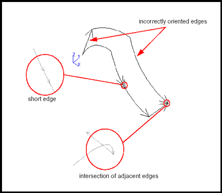
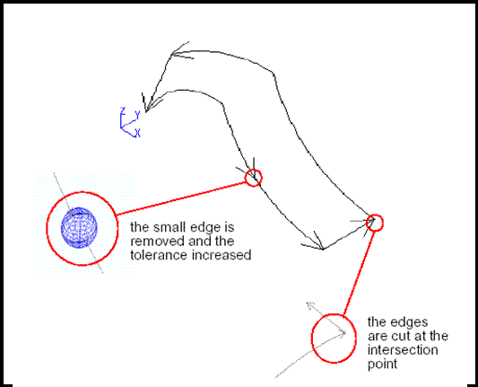
Here are a few examples of typical problems with illustrations of how Shape Healing deals with them:

  • Face with missing seam edge
    • problem: face on a periodical surface is limited by wires which make a full trip around the surface. These wires are closed in 3d but not closed in parametric space of the surface. This is not valid in Open CASCADE.
    • solution: Shape Healing fixes this face by inserting seam edge which combines two open wires and thus closes the parametric space. Note that internal wires are processed correctly.
  • Wrong orientation of wires
    • problem: wires on face have incorrect orientation, so that interior and outer parts of the face are mixed.
    • solution: Shape Healing recovers correct orientation of wires.
  • Self-intersecting wire
    • problem: face is invalid because its boundary wire has self-intersection (on two adjacent edges).
    • solution: shape Healing cuts intersecting edges at intersection points thus making boundary valid.
  • Lacking edge
    • problem: there is a gap between two edges in the wire, so that wire is not closed.
    • solution: Shape Healing closes a gap by inserting lacking edge.

Toolkit Structure

Shape Healing currently includes several packages that are designed to help you to:

  • analyze shape characteristics and, in particular, identify shapes that do not comply with Open CASCADE Technology validity rules;
  • fix some of the problems shapes may have;
  • upgrade shape characteristics for users needs, for example a C0 supporting surface can be upgraded so that it becomes C1 continuous.

The following diagram shows dependencies of API packages:

Shape Healing packages

Each sub-domain has its own scope of functionality:

  • analysis – exploring shape properties, computing shape features, detecting violation of OCCT requirements (shape itself is not modified);
  • fixing – fixing shape to meet the OCCT requirements (the shape may change its original form: modifying, removing, constructing sub-shapes, etc.);
  • upgrade – shape improvement for better usability in Open CASCADE Technology or other algorithms (the shape is replaced with a new one, but geometrically they are the same);
  • customization – modifying shape representation to fit specific needs (shape is not modified, only the form of its representation is modified);
  • processing – mechanism of managing shape modification via a user-editable resource file.

Message management is used for creating messages, filling them with various parameters and storing them in the trace file. This tool provides functionality for attaching messages to the shapes for deferred analysis of various run-time events. In this document only general principles of using Shape Healing will be described. For more detailed information, see the corresponding header files.

Tools responsible for analysis, fixing and upgrading of shapes can give the information about how these operations were performed. This information can be obtained by the user with the help of mechanism of status querying.

Querying the statuses

Each fixing and upgrading tool has its own status, which is reset when their methods are called. The status can contain several flags, which give the information about how the method was performed. For exploring the statuses, a set of methods named StatusXXX() is provided (ShapeFix_Wire::StatusReorder() for instance). These methods accept enumeration ShapeExtend_Status and return True if the status has the corresponding flag set. The meaning of flags for each method is described below.

The status may contain a set of Boolean flags (internally represented by bits). Flags are coded by enumeration ShapeExtend_Status. This enumeration provides the following families of statuses:

  • ShapeExtend_OK – The situation is OK, no operation is necessary and has not been performed.
  • ShapeExtend_DONE – The operation has been successfully performed.
  • ShapeExtend_FAIL – An error has occurred during operation.

It is possible to test the status for the presence of some flag(s), using StatusXXX() method(s) provided by the class:

if (object.StatusXXX (ShapeExtend_DONE))
{
// something was done
}

8 'DONE' and 8 'FAIL' flags, named ShapeExtend_DONE1 ... ShapeExtend_FAIL8, are defined for a detailed analysis of the encountered situation. Each method assigns its own meaning to each flag, documented in the header for that method. There are also three enumerative values used for testing several flags at a time:

  • ShapeExtend_OK – if no flags have been set;
  • ShapeExtend_DONE – if at least one ShapeExtend_DONEi has been set;
  • ShapeExtend_FAIL – if at least one ShapeExtend_FAILi has been set.

Repair

Algorithms for fixing problematic (violating the OCCT requirements) shapes are placed in package ShapeFix.

Each class of package ShapeFix deals with one certain type of shapes or with some family of problems.

There is no necessity for you to detect problems before using ShapeFix because all components of package ShapeFix make an analysis of existing problems before fixing them by a corresponding tool from package of ShapeAnalysis and then fix the discovered problems.

The ShapeFix package currently includes functions that:

  • add a 2D curve or a 3D curve where one is missing,
  • correct a deviation of a 2D curve from a 3D curve when it exceeds a given tolerance value,
  • limit the tolerance value of shapes within a given range,
  • set a given tolerance value for shapes,
  • repair the connections between adjacent edges of a wire,
  • correct self-intersecting wires,
  • add seam edges,
  • correct gaps between 3D and 2D curves,
  • merge and remove small edges,
  • correct orientation of shells and solids.

Basic Shape Repair

The simplest way for fixing shapes is to use classes ShapeFix_Shape and ShapeFix_Wireframe on a whole shape with default parameters. A combination of these tools can fix most of the problems that shapes may have. The sequence of actions is as follows:

  1. Create tool ShapeFix_Shape and initialize it by shape:
    Handle(ShapeFix_Shape) aFixShape = new ShapeFix_Shape();
    aFixShape->Init (theShape);
  2. Set the basic precision, the maximum allowed tolerance, the minimal allowed tolerance:

    aFixShape->SetPrecision (thePrec);
    aFixShape->SetMaxTolerance (theMaxTol);
    aFixShape->SetMinTolerance (theMintol);

    where:

    • thePrec – basic precision.
    • theMaxTol – maximum allowed tolerance. All problems will be detected for cases when a dimension of invalidity is larger than the basic precision or a tolerance of sub-shape on that problem is detected. The maximum tolerance value limits the increasing tolerance for fixing a problem such as fix of not connected and self-intersected wires. If a value larger than the maximum allowed tolerance is necessary for correcting a detected problem the problem can not be fixed. The maximal tolerance is not taking into account during computation of tolerance of edges in ShapeFix_SameParameter() method and ShapeFix_Edge::FixVertexTolerance() method. See Repairing tool for edges for details.
    • theMintol – minimal allowed tolerance. It defines the minimal allowed length of edges. Detected edges having length less than the specified minimal tolerance will be removed if ModifyTopologyMode in Repairing tool for wires is set to true. See Repairing tool for wires for details.
  3. Launch fixing:
    aFixShape->Perform();
  4. Get the result:

    TopoDS_Shape aResult = aFixShape->Shape();

    In some cases using only ShapeFix_Shape can be insufficient. It is possible to use tools for merging and removing small edges and fixing gaps between 2D and 3D curves.

  5. Create ShapeFix_Wireframe tool and initialize it by shape:

    Handle(ShapeFix_Wireframe) aFixWire = new ShapeFix_Wireframe (theShape);

    or:

    Handle(ShapeFix_Wireframe) aFixWire = new ShapeFix_Wireframe();
    aFixWire->Load (theShape);
  6. Set the basic precision and the maximum allowed tolerance:
    aFixWire->SetPrecision (thePrec);
    aFixWire->SetMaxTolerance (theMaxTol);

See the description for thePrec and theMaxTol above.

  1. Merge and remove small edges:
    aFixWire->DropSmallEdgesMode() = true;
    aFixWire->FixSmallEdges();

Note: Small edges are not removed with the default mode, but in many cases removing small edges is very useful for fixing a shape.

  1. Fix gaps for 2D and 3D curves
    aFixWire->FixWireGaps();
  2. Get the result
    TopoDS_Shape aResult = aFixWire->Shape();

Shape Correction

If you do not want to make fixes on the whole shape or make a definite set of fixes you can set flags for separate fix cases (marking them ON or OFF) and you can also use classes for fixing specific types of sub-shapes such as solids, shells, faces, wires, etc.

For each type of sub-shapes there are specific types of fixing tools such as ShapeFix_Solid, ShapeFix_Shell, ShapeFix_Face, ShapeFix_Wire, etc.

Fixing sub-shapes

If you want to make a fix on one sub-shape of a certain shape it is possible to take the following steps:

  • create a tool for a specified sub-shape type and initialize this tool by the sub-shape;
  • create a tool for rebuilding the shape and initialize it by the whole shape (section 5.1);
  • set a tool for rebuilding the shape in the tool for fixing the sub-shape;
  • fix the sub-shape;
  • get the resulting whole shape containing a new corrected sub-shape.

For example, in the following way it is possible to fix face theFace1 of shape theShape1:

// create tools for fixing a face
Handle(ShapeFix_Face) aFixFace = new ShapeFix_Face();
// create tool for rebuilding a shape and initialize it by shape
Handle(ShapeBuild_ReShape) aReshapeContext = new ShapeBuild_ReShape();
aReshapeContext->Apply (theShape1);
// set a tool for rebuilding a shape in the tool for fixing
aFixFace->SetContext (aReshapeContext);
// initialize the fixing tool by one face
aFixFace->Init (theFace1);
// fix the set face
aFixFace->Perform();
// get the result; resulting shape contains the fixed face
TopoDS_Shape aNewShape = aReshapeContext->Apply (theShape1);

A set of required fixes and invalid sub-shapes can be obtained with the help of tools responsible for the analysis of shape validity (section 3.2).

Repairing tools

Each class of package ShapeFix deals with one certain type of shapes or with a family of problems. Each repairing tool makes fixes for the specified shape and its sub-shapes with the help of method Perform() containing an optimal set of fixes. The execution of these fixes in the method Perform can be managed with help of a set of control flags (fixes can be either forced or forbidden).

General Workflow

The following sequence of actions should be applied to perform fixes:

  1. Create a tool.
  2. Set the following values:
    • the working precision by method SetPrecision() (default 1.e-7);
    • set the maximum allowed tolerance by method SetMaxTolerance() (by default it is equal to the working precision);
    • set the minimum tolerance by method SetMinTolerance() (by default it is equal to the working precision);
    • set a tool for rebuilding shapes after the modification (tool ShapeBuild_ReShape) by method SetContext(); for separate faces, wires and edges this tool is set optionally;
    • to force or forbid some of fixes, set the corresponding flag to 0 or 1.
  3. Initialize the tool by the shape with the help of methods Init() or Load().
  4. Use method Perform() or create a custom set of fixes.
  5. Check the statuses of fixes by the general method Status or specialized methods Status_ (for example StatusSelfIntersection (ShapeExtentd_DONE)). See the description of statuses below.
  6. Get the result in two ways:
    • with help of a special method Shape(), Face(), Wire(), Edge().
    • from the rebuilding tool by method Apply() (for access to rebuilding tool use method Context()):
      TopoDS_Shape aResultShape = aFixTool->Context()->Apply (theInitialShape);

Modification history for the shape and its sub-shapes can be obtained from the tool for shape re-building (ShapeBuild_ReShape).

TopoDS_Shape aModifSubshape = aFixTool->Context()->Apply (theInitSubShape);

Flags Management

The flags Fix...Mode() are used to control the execution of fixing procedures from the API fixing methods. By default, these flags have values equal to -1, this means that the corresponding procedure will either be called or not called, depending on the situation. If the flag is set to 1, the procedure is executed anyway; if the flag is 0, the procedure is not executed. The name of the flag corresponds to the fixing procedure that is controlled. For each fixing tool there exists its own set of flags. To set a flag to the desired value, get a tool containing this flag and set the flag to the required value.

For example, it is possible to forbid performing fixes to remove small edges - FixSmall:

Handle(ShapeFix_Shape) aFixShape = new ShapeFix_Shape (theShape);
aFixShape->FixWireTool()->FixSmallMode() = 0;
if (aFixShape->Perform())
{
TopoDS_Shape aResShape = aFixShape->Shape();
}

Repairing tool for shapes

Class ShapeFix_Shape allows using repairing tools for all sub-shapes of a shape. It provides access to all repairing tools for fixing sub-shapes of the specified shape and to all control flags from these tools.

For example, it is possible to force the removal of invalid 2D curves from a face:

TopoDS_Face theFace = ...; // face with invalid 2D curves.
// creation of tool and its initialization by shape
Handle(ShapeFix_Shape) aFixShape = new ShapeFix_Shape (theFace);
// set work precision and max allowed tolerance
aFixShape->SetPrecision (thePrec);
aFixShape->SetMaxTolerance (theMaxTol);
//set the value of flag for forcing the removal of 2D curves
aFixShape->FixWireTool()->FixRemovePCurveMode() = 1;
// reform fixes
aFixShape->Perform();
// getting the result
if (aFixShape->Status (ShapeExtend_DONE))
{
std::cout << "Shape was fixed\n";
TopoDS_Shape aResFace = aFixShape->Shape();
}
else if (aFixShape->Status (ShapeExtend_FAIL))
{
std::cout << "Shape could not be fixed\n";
}
else if (aFixShape->Status (ShapeExtent_OK))
{
std::cout << "Initial face is valid with specified precision =" << thePrec << std::endl;
}

Repairing tool for solids

Class ShapeFix_Solid allows fixing solids and building a solid from a shell to obtain a valid solid with a finite volume. The tool ShapeFix_Shell is used for correction of shells belonging to a solid.

This tool has the following control flags:

  • FixShellMode – Mode for applying fixes of ShapeFix_Shell, True by default.
  • CreateOpenShellMode – If it is equal to true solids are created from open shells, else solids are created from closed shells only, False by default.

Repairing tool for shells

Class ShapeFix_Shell allows fixing wrong orientation of faces in a shell. It changes the orientation of faces in the shell so that all faces in the shell have coherent orientations. If it is impossible to orient all faces in the shell (like in case of Möbius strip), then a few manifold or non-manifold shells will be created depending on the specified Non-manifold mode. The ShapeFix_Face tool is used to correct faces in the shell. This tool has the following control flags:

  • FixFaceMode – mode for applying the fixes of ShapeFix_Face, True by default.
  • FixOrientationMode – mode for applying a fix for the orientation of faces in the shell.

Repairing tool for faces

Class ShapeFix_Face allows fixing the problems connected with wires of a face. It allows controlling the creation of a face (adding wires), and fixing wires by means of tool ShapeFix_Wire. When a wire is added to a face, it can be reordered and degenerated edges can be fixed. This is performed or not depending on the user-defined flags (by default, False). The following fixes are available:

  • Fixing of wires orientation on the face. If the face has no wire, the natural bounds are computed. If the face is on a spherical surface and has two or more wires on it describing holes, the natural bounds are added. In case of a single wire, it is made to be an outer one. If the face has several wires, they are oriented to lay one outside another (if possible). If the supporting surface is periodic, 2D curves of internal wires can be shifted on integer number of periods to put them inside the outer wire.
  • fixing the case when the face on the closed surface is defined by a set of closed wires, and the seam is missing (this is not valid in OCCT). In that case, these wires are connected by means of seam edges into the same wire.

This tool has the following control flags:

  • FixWireMode – mode for applying fixes of a wire, True by default.
  • FixOrientationMode – mode for orienting a wire to border a limited square, True by default.
  • FixAddNaturalBoundMode – mode for adding natural bounds to a face, False by default.
  • FixMissingSeamMode – mode to fix a missing seam, True by default. If True, tries to insert a seam.
  • FixSmallAreaWireMode – mode to fix a small-area wire, False by default. If True, drops wires bounding small areas.
TopoDS_Face theFace = ...;
TopoDS_Wire theWire = ...;
// Create a tool and adds a wire to the face
ShapeFix_Face aFixShape (theFace);
aFixShape.Add (theWire);
// use method Perform to fix the wire and the face
aFixShape.Perform();
// or make a separate fix for the orientation of wire on the face
aFixShape.FixOrientation();
// Get the resulting face
TopoDS_Face aNewFace = aFixShape.Face();

Repairing tool for wires

Class ShapeFix_Wire allows fixing a wire. Its method Perform() performs all the available fixes in addition to the geometric filling of gaps. The geometric filling of gaps can be made with the help of the tool for fixing the wireframe of shape ShapeFix_Wireframe.

The fixing order and the default behavior of Perform() is as follows:

  • Edges in the wire are reordered by FixReorder. Most of fixing methods expect edges in a wire to be ordered, so it is necessary to make call to FixReorder() before making any other fixes. Even if it is forbidden, the analysis of whether the wire is ordered or not is performed anyway.
  • Small edges are removed by FixSmall.
  • Edges in the wire are connected (topologically) by FixConnected (if the wire is ordered).
  • Edges (3Dcurves and 2D curves) are fixed by FixEdgeCurves (without FixShifted if the wire is not ordered).
  • Degenerated edges are added by FixDegenerated (if the wire is ordered).
  • Self-intersection is fixed by FixSelfIntersection (if the wire is ordered and ClosedMode is True).
  • Lacking edges are fixed by FixLacking (if the wire is ordered).

The flag ClosedWireMode specifies whether the wire is (or should be) closed or not. If that flag is True (by default), fixes that require or force connection between edges are also executed for the last and the first edges.

The fixing methods can be turned on/off by using their corresponding control flags:

  • FixReorderMode,
  • FixSmallMode,
  • FixConnectedMode,
  • FixEdgeCurvesMode,
  • FixDegeneratedMode,
  • FixSelfIntersectionMode

Some fixes can be made in three ways:

  • Increasing the tolerance of an edge or a vertex.
  • Changing topology (adding/removing/replacing an edge in the wire and/or replacing the vertex in the edge, copying the edge etc.).
  • Changing geometry (shifting a vertex or adjusting ends of an edge curve to vertices, or recomputing a 3D curve or 2D curves of the edge).

When it is possible to make a fix in more than one way (e.g., either by increasing the tolerance or shifting a vertex), it is chosen according to the user-defined flags:

  • ModifyTopologyMode – allows modifying topology. False by default.
  • ModifyGeometryMode – allows modifying geometry. Now this flag is used only in fixing self-intersecting edges (allows to modify 2D curves) and is True by default.

Fixing disordered edges

FixReorder is necessary for most other fixes (but is not necessary for Open CASCADE Technology). It checks whether edges in the wire go in a sequential order (the end of a preceding edge is the start of a following one). If it is not so, an attempt to reorder the edges is made.

Fixing small edges

FixSmall method searches for the edges, which have a length less than the given value (degenerated edges are ignored). If such an edge is found, it is removed provided that one of the following conditions is satisfied:

  • both end vertices of that edge are one and the same vertex,
  • end vertices of the edge are different, but the flag ModifyTopologyMode is True; in the latter case, method FixConnected is applied to the preceding and the following edges to ensure their connection.

Fixing disconnected edges

FixConnected method forces two adjacent edges to share the same common vertex (if they do not have a common one). It checks whether the end vertex of the preceding edge coincides with the start vertex of the following edge with the given precision, and then creates a new vertex and sets it as a common vertex for the fixed edges. At that point, edges are copied, hence the wire topology is changed (regardless of the ModifyTopologyMode flag). If the vertices do not coincide, this method fails.

Fixing the consistency of edge curves

FixEdgeCurves method performs a set of fixes dealing with 3D curves and 2D curves of edges in a wire.

These fixes will be activated with the help of a set of fixes from the repairing tool for edges called ShapeFix_Edge. Each of these fixes can be forced or forbidden by means of setting the corresponding flag to either True or False.

The mentioned fixes and the conditions of their execution are:

  • fixing a disoriented 2D curve by call to ShapeFix_Edge::FixReversed2d – if not forbidden by flag FixReversed2dMode;
  • removing a wrong 2D curve by call to ShapeFix_Edge::FixRemovePCurve – only if forced by flag FixRemovePCurveMode;
  • fixing a missing 2D curve by call to ShapeFix_Edge::FixAddPCurve – if not forbidden by flag FixAddPCurveMode;
  • removing a wrong 3D curve by call to ShapeFix_Edge::FixRemoveCurve3d – only if forced by flag FixRemoveCurve3dMode;
  • fixing a missing 3D curve by call to ShapeFix_Edge::FixAddCurve3d – if not forbidden by flag FixAddCurve3dMode;
  • fixing 2D curves of seam edges – if not forbidden by flag FixSeamMode;
  • fixing 2D curves which can be shifted at an integer number of periods on the closed surface by call to ShapeFix_Edge::FixShifted – if not forbidden by flag FixShiftedMode.

This fix is required if 2D curves of some edges in a wire lying on a closed surface were recomputed from 3D curves. In that case, the 2D curve for the edge, which goes along the seam of the surface, can be incorrectly shifted at an integer number of periods. The method FixShifted detects such cases and shifts wrong 2D curves back, ensuring that the 2D curves of the edges in the wire are connected.

  • fixing the SameParameter problem by call to ShapeFix_Edge::FixSameParameter – if not forbidden by flag FixSameParameterMode.

Fixing degenerated edges

FixDegenerated method checks whether an edge in a wire lies on a degenerated point of the supporting surface, or whether there is a degenerated point between the edges. If one of these cases is detected for any edge, a new degenerated edge is created and it replaces the current edge in the first case or is added to the wire in the second case. The newly created degenerated edge has a straight 2D curve, which goes from the end of the 2D curve of the preceding edge to the start of the following one.

Fixing intersections of 2D curves of the edges

FixSelfIntersection method detects and fixes the following problems:

  • Self-intersection of 2D curves of individual edges. If the flag ModifyGeometryMode() is False this fix will be performed by increasing the tolerance of one of end vertices to a value less then MaxTolerance().
  • Intersection of 2D curves of each of the two adjacent edges (except the first and the last edges if the flag ClosedWireMode is False). If such intersection is found, the common vertex is modified in order to comprise the intersection point. If the flag ModifyTopologyMode is False this fix will be performed by increasing the tolerance of the vertex to a value less then MaxTolerance().
  • Intersection of 2D curves of non-adjacent edges. If such intersection is found the tolerance of the nearest vertex is increased to comprise the intersection point. If such increase cannot be done with a tolerance less than MaxTolerance this fix will not be performed.

Fixing a lacking edge

FixLacking method checks whether a wire is not closed in the parametric space of the surface (while it can be closed in 3D). This is done by checking whether the gap between 2D curves of each of the two adjacent edges in the wire is smaller than the tolerance of the corresponding vertex. The algorithm computes the gap between the edges, analyses positional relationship of the ends of these edges and (if possible) tries to insert a new edge into the gap or increases the tolerance.

Fixing gaps in 2D and 3D wire by geometric filling

The following methods check gaps between the ends of 2D or 3D curves of adjacent edges:

  • Method FixGap2d moves the ends of 2D curves to the middle point.
  • Method FixGaps3d moves the ends of 3D curves to a common vertex.

Boolean flag FixGapsByRanges is used to activate an additional mode applied before converting to B-Splines. When this mode is on, methods try to find the most precise intersection of curves, or the most precise projection of a target point, or an extremity point between two curves (to modify their parametric range accordingly). This mode is off by default. Independently of the additional mode described above, if gaps remain, these methods convert curves to B-Spline form and shift their ends if a gap is detected.

Example: A custom set of fixes

Let us create a custom set of fixes as an example:

TopoDS_Face theFace = ...;
TopoDS_Wire theWire = ...;
Standard_Real aPrecision = 1e-04;
ShapeFix_Wire aFixWire (theWire, theFace, aPrecision);
// create a tool and loads objects into it
aFixWire.FixReorder();
// order edges in the wire so that each edge starts at the end of the one before it
aFixWire.FixConnected();
// force all adjacent edges to share the same vertex
bool toLockVertex = true;
if (aFixWire.FixSmall (toLockVertex, aPrecision))
{
// removed all edges which are shorter than the given precision and have the same vertex at both ends
}
if (aFixWire.FixSelfIntersection())
{
// fixed self-intersecting edges and intersecting adjacent edges
std::cout << "Wire was slightly self-intersecting. Repaired\n";
}
if (aFixWire.FixLacking (false))
{
// inserted edges to connect adjacent non-continuous edges
}
TopoDS_Wire aNewWire = aFixWire.Wire();
// return the corrected wire

Example: Correction of a wire

Let us correct the following wire:

Initial shape

It is necessary to apply the tools for the analysis of wire validity to check that:

  • the edges are correctly oriented;
  • there are no edges that are too short;
  • there are no intersecting adjacent edges; and then immediately apply fixing tools.
TopoDS_Face theFace = ...;
TopoDS_Wire theWire = ...;
Standard_Real aPrecision = 1e-04;
ShapeAnalysis_Wire aCheckWire (theWire, theFace, aPrecision);
ShapeFix_Wire aFixWire (theWire, theFace, aPrecision);
if (aCheckWire.CheckOrder())
{
std::cout << "Some edges in the wire need to be reordered\n";
// two edges are incorrectly oriented
aFixWire.FixReorder();
std::cout << "Reordering is done\n";
}
// their orientation is corrected
if (aCheckWire.CheckSmall (aPrecision))
{
std::cout << "Wire contains edge(s) shorter than " << aPrecision << std::endl;
// an edge that is shorter than the given tolerance is found
Standard_Boolean LockVertex = Standard_True;
if (aFixWire.FixSmall (LockVertex, aPrecision))
{
std::cout << "Edges shorter than " << aPrecision << " have been removed\n";
// the edge is removed
}
}
if (aCheckWire.CheckSelfIntersection())
{
std::cout << "Wire has self-intersecting or intersecting adjacent edges\n";
// two intersecting adjacent edges are found
if (aFixWire.FixSelfIntersection())
{
std::cout << "Wire was slightly self-intersecting. Repaired\n";
// The edges are cut at the intersection point so that they no longer intersect.
}
}

As the result all failures have been fixed.

Resulting shape

Repairing tool for edges

Class ShapeFix_Edge provides tools for fixing invalid edges. The following geometric and/or topological inconsistencies are detected and fixed:

  • missing 3D curve or 2D curve,
  • mismatching orientation of a 3D curve and a 2D curve,
  • incorrect SameParameter flag (curve deviation is greater than the edge tolerance).

Each fixing method first checks whether the problem exists using methods of the ShapeAnalysis_Edge class. If the problem is not detected, nothing is done. This tool does not have the method Perform().

To see how this tool works, it is possible to take an edge, where the maximum deviation between the 3D curve and 2D curve P1 is greater than the edge tolerance.

Initial shape

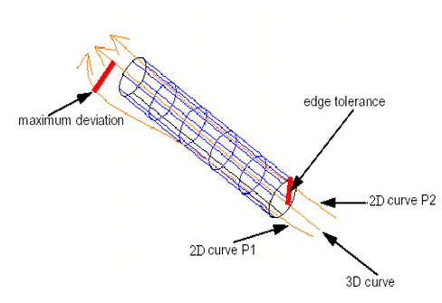
First it is necessary to apply the tool for checking the edge validity to find that the maximum deviation between pcurve and 3D curve is greater than tolerance. Then we can use the repairing tool to increase the tolerance and make the deviation acceptable.

TopoDS_Edge theEdge = ...;
ShapeAnalysis_Edge aCheckEdge;
Standard_Real aMaxDev = 0.0;
if (aCheckEdge.CheckSameParameter (theEdge, aMaxDev))
{
std::cout << "Incorrect SameParameter flag\n"
<< "Maximum deviation " << aMaxDev << ", tolerance " << BRep_Tool::Tolerance (theEdge) << std::endl;
ShapeFix_Edge aFixEdge;
aFixEdge.FixSameParameter();
std::cout << "New tolerance " << BRep_Tool::Tolerance (theEdge) << std::endl;
}
Resulting shape

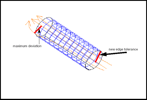
As the result, the edge tolerance has been increased.

Repairing tool for the wireframe of a shape

Class ShapeFix_Wireframe provides methods for geometric fixing of gaps and merging small edges in a shape. This class performs the following operations:

  • fills gaps in the 2D and 3D wireframe of a shape.
  • merges and removes small edges.

Fixing of small edges can be managed with the help of two flags:

  • ModeDropSmallEdges() – mode for removing small edges that can not be merged, by default it is equal to Standard_False.
  • LimitAngle – maximum possible angle for merging two adjacent edges, by default no limit angle is applied (-1).

To perform fixes it is necessary to:

  • create a tool and initialize it by shape,
  • set the working precision problems will be detected with and the maximum allowed tolerance
  • perform fixes
// creation of a tool
Handle(ShapeFix_Wireframe) aFixWireframe = new ShapeFix_Wireframe (theShape);
// set the working precision problems will be detected with and the maximum allowed tolerance
aFixWireframe->SetPrecision (thePrec);
aFixWireframe->SetMaxTolerance (theMaxTol);
// fixing of gaps
aFixWireframe->FixWireGaps();
// fixing of small edges
// setting of the drop mode for the fixing of small edges and max possible angle between merged edges
aFixWireframe->ModeDropSmallEdges = true;
aFixWireframe->SetLimliteAngle (theAngle);
// performing the fix
aFixWireframe->FixSmallEdges();
// getting the result
TopoDS_Shape aResShape = aFixWireframe->Shape();

It is desirable that a shape is topologically correct before applying the methods of this class.

Tool for removing small faces from a shape

Class ShapeFix_FixSmallFaceThis tool is intended for dropping small faces from the shape. The following cases are processed:

  • Spot face: if the size of the face is less than the given precision;
  • Strip face: if the size of the face in one dimension is less then the given precision.

The sequence of actions for performing the fix is the same as for the fixes described above:

// creation of a tool
Handle(ShapeFix_FixSmallFace) aFixSmallFace = new ShapeFix_FixSmallFace (theShape);
// setting of tolerances
aFixSmallFace->SetPrecision (thePrec);
aFixSmallFace->SetMaxTolerance (theMaxTol);
// performing fixes
aFixSmallFace.Perform();
// getting the result
TopoDS_Shape aResShape = aFixSmallFace.FixShape();

Tool to modify tolerances of shapes (Class ShapeFix_ShapeTolerance)

This tool provides a functionality to set tolerances of a shape and its sub-shapes. In Open CASCADE Technology only vertices, edges and faces have tolerances.

This tool allows processing each concrete type of sub-shapes or all types at a time. You set the tolerance functionality as follows:

  • set a tolerance for sub-shapes, by method SetTolerance,
  • limit tolerances with given ranges, by method LimitTolerance.
// creation of a tool
ShapeFix_ShapeTolerance aFixToler;
// setting a specified tolerance on shape and all of its sub-shapes
aFixToler.SetTolerance (theShape, theToler);
// setting a specified tolerance for vertices only
aFixToler.SetTolerance (theShape, theToler, TopAbs_VERTEX);
// limiting the tolerance on the shape and its sub-shapes between minimum and maximum tolerances
aFixToler.LimitTolerance (theShape, theTolerMin, theTolerMax);

Analysis

Analysis of shape validity

The ShapeAnalysis package provides tools for the analysis of topological shapes. It is not necessary to check a shape by these tools before the execution of repairing tools because these tools are used for the analysis before performing fixes inside the repairing tools. However, if you want, these tools can be used for detecting some of shape problems independently from the repairing tools.

It can be done in the following way:

  • create an analysis tool;
  • initialize it by shape and set a tolerance problems will be detected with if it is necessary;
  • check the problem that interests you.
TopoDS_Face theFace = ...;
// create a tool for analyzing an edge
ShapeAnalysis_Edge aCheckEdge;
for (TopExp_Explorer anExp (theFace, TopAbs_EDGE); anExp.More(); anExp.Next())
{
TopoDS_Edge anEdge = TopoDS::Edge (anExp.Current());
if (!aCheckEdge.HasCurve3d (anEdge))
{
std::cout << "Edge has no 3D curve\n";
}
}

Analysis of orientation of wires on a face

It is possible to check whether a face has an outer boundary with the help of method ShapeAnalysis::IsOuterBound.

TopoDS_Face theFace = ...; // analyzed face
if (!ShapeAnalysis::IsOuterBound (theFace))
{
std::cout << "Face has not outer boundary\n";
}

Analysis of wire validity

Class ShapeAnalysis_Wire is intended to analyze a wire. It provides functionalities both to explore wire properties and to check its conformance to Open CASCADE Technology requirements. These functionalities include:

  • checking the order of edges in the wire,
  • checking for the presence of small edges (with a length less than the given value),
  • checking for the presence of disconnected edges (adjacent edges having different vertices),
  • checking the consistency of edge curves,
  • checking for the presence or missing of degenerated edges,
  • checking for the presence of self-intersecting edges and intersecting edges (edges intersection is understood as intersection of their 2D curves),
  • checking for lacking edges to fill gaps in the surface parametric space,
  • analyzing the wire orientation (to define the outer or the inner bound on the face),
  • analyzing the orientation of the shape (edge or wire) being added to an already existing wire.

Note that all checking operations except for the first one are based on the assumption that edges in the wire are ordered. Thus, if the wire is detected as non-ordered it is necessary to order it before calling other checking operations. This can be done, for example, with the help of the ShapeFix_Wire::FixOrder() method.

This tool should be initialized with wire, face (or a surface with a location) or precision. Once the tool has been initialized, it is possible to perform the necessary checking operations. In order to obtain all information on a wire at a time the global method Perform is provided. It calls all other API checking operations to check each separate case.

API methods check for corresponding cases only, the value and the status they return can be analyzed to understand whether the case was detected or not.

Some methods in this class are:

  • CheckOrder checks whether edges in the wire are in the right order;
  • CheckConnected checks whether edges are disconnected;
  • CheckSmall checks whether there are edges that are shorter than the given value;
  • CheckSelfIntersection checks, whether there are self-intersecting or adjacent intersecting edges. If the intersection takes place due to nonadjacent edges, it is not detected.

This class maintains status management. Each API method stores the status of its last execution which can be queried by the corresponding Status..() method. In addition, each API method returns a Boolean value, which is True when a case being analyzed is detected (with the set ShapeExtend_DONE status), otherwise it is False.

TopoDS_Face theFace = ...;
TopoDS_Wire theWire = ...;
Standard_Real aPrecision = 1e-04;
ShapeAnalysis_Wire aCheckWire (theWire, theFace, aPrecision);
// create a tool and load objects into it
if (aCheckWire.CheckOrder())
{
std::cout << "Some edges in the wire need to be reordered\n"
<< "Please ensure that all the edges are correctly ordered before further analysis\n";
return;
}
if (aCheckWire.CheckSmall (aPrecision))
{
std::cout << "Wire contains edge(s) shorter than " << aPrecision << std::endl;
}
if (aCheckWire.CheckConnected())
{
std::cout << "Wire is disconnected\n";
}
if (aCheckWire.CheckSelfIntersection())
{
std::cout << "Wire has self-intersecting or intersecting adjacent edges\n";
}

Analysis of edge validity

Class ShapeAnalysis_Edge is intended to analyze edges. It provides the following functionalities to work with an edge:

  • querying geometric representations (3D curve and pcurve(s) on a given face or surface),
  • querying topological sub-shapes (bounding vertices),
  • checking overlapping edges,
  • analyzing the curves consistency:
    • mutual orientation of the 3D curve and 2D curve (co-directions or opposite directions),
    • correspondence of 3D and 2D curves to vertices.

This class supports status management described above.

TopoDS_Face theFace = ...;
// create a tool for analyzing an edge
ShapeAnalysis_Edge aCheckEdge;
for (TopExp_Explorer anExp (theFace, TopAbs_EDGE); anExp.More(); anExp.Next())
{
TopoDS_Edge anEdge = TopoDS::Edge (anExp.Current());
if (!aCheckEdge.HasCurve3d (anEdge))
{
std::cout << "Edge has no 3D curve\n";
}
Handle(Geom2d_Curve) aPCurve;
Standard_Real aPFirst = 0.0, aPLast = 0.0;
if (aCheckEdge.PCurve (anEdge, theFace, aPCurve, aPFirst, aPLast, Standard_False))
{
// print the pcurve and its range on the given face
std::cout << "Pcurve range [" << aPFirst << ", " << aPLast << "]\n";
}
Standard_Real aMaxDev = 0.0;
if (aCheckEdge.CheckSameParameter (anEdge, aMaxDev))
{
// check the consistency of all the curves in the edge
std::cout << "Incorrect SameParameter flag\n";
}
std::cout << "Maximum deviation " << aMaxDev << ", tolerance"
<< BRep_Tool::Tolerance (anEdge) << std::endl;
}
// check the overlapping of two edges
TopoDS_Edge theEdge1 = ...;
TopoDS_Edge theEdge2 = ...;
Standard_Real theDomainDist = 0.0;
ShapeAnalysis_Edge aCheckEdge;
Standard_Real aTolOverlap = 0.0;
if (aCheckEdge.CheckOverlapping (theEdge1, theEdge2, aTolOverlap, theDomainDist))
{
std::cout << "Edges are overlapped with tolerance = " << aTolOverlap << std::endl;
std::cout << "Domain of overlapping =" << theDomainDist << std::endl;
}

Analysis of presence of small faces

Class ShapeAnalysis_CheckSmallFace class is intended for analyzing small faces from the shape using the following methods:

  • CheckSpotFace() checks if the size of the face is less than the given precision;
  • CheckStripFace checks if the size of the face in one dimension is less than the given precision.
TopoDS_Shape theShape = ...; // checked shape
// creation of a tool
ShapeAnalysis_CheckSmallFace aCheckSmallFace;
// exploring the shape on faces and checking each face
Standard_Integer aNbSmallfaces = 0;
for (TopExp_Explorer anExp (theShape, TopAbs_FACE); anExp.More(); anExp.Next())
{
TopoDS_Face aFace = TopoDS::Face (anExp.Current());
TopoDS_Edge anEdge1, anEdge2;
if (aCheckSmallFace.CheckSpotFace (aFace, thePrec)
|| aCheckSmallFace.CheckStripFace (aFace, anEdge1, anEdge2, thePrec))
{
++aNbSmallfaces;
}
}
if (aNbSmallfaces != 0)
{
std::cout << "Number of small faces in the shape = " << aNbSmallfaces << std::endl;
}

Analysis of shell validity and closure

Class ShapeAnalysis_Shell allows checking the orientation of edges in a manifold shell. With the help of this tool, free edges (edges entered into one face) and bad edges (edges entered into the shell twice with the same orientation) can be found. By occurrence of bad and free edges a conclusion about the shell validity and the closure of the shell can be made.

TopoDS_Shell theShell = ...; // checked shape
ShapeAnalysis_Shell aCheckShell (theShell);
// analysis of the shell; second parameter is set to True for getting free edges
aCheckShell.CheckOrientedShells (theShell, true);
// getting the result of analysis
if (aCheckShell.HasBadEdges())
{
std::cout << "Shell is invalid\n";
TopoDS_Compound badEdges = aCheckShell.BadEdges();
}
if (aCheckShell.HasFreeEdges())
{
std::cout << "Shell is open\n";
TopoDS_Compound freeEdges = aCheckShell.FreeEdges();
}

Analysis of shape properties

Analysis of tolerance on shape

Class ShapeAnalysis_ShapeTolerance allows computing tolerances of the shape and its sub-shapes. In Open CASCADE Technology only vertices, edges and faces have tolerances:

This tool allows analyzing each concrete type of sub-shapes or all types at a time. The analysis of tolerance functionality is the following:

  • computing the minimum, maximum and average tolerances of sub-shapes,
  • finding sub-shapes with tolerances exceeding the given value,
  • finding sub-shapes with tolerances in the given range.
TopoDS_Shape theShape = ...;
ShapeAnalysis_ShapeTolerance aCheckToler;
Standard_Real anAverageOnShape = aCheckToler.Tolerance (theShape, 0);
std::cout << "Average tolerance of the shape is " << anAverageOnShape << std::endl;
Standard_Real aMinOnEdge = aCheckToler.Tolerance (theShape, -1, TopAbs_EDGE);
std::cout << "Minimum tolerance of the edges is " << aMinOnEdge << std::endl;
Standard_Real aMaxOnVertex = aCheckToler.Tolerance (theShape, 1, TopAbs_VERTEX);
std::cout << "Maximum tolerance of the vertices is " << aMaxOnVertex << std::endl;
Standard_Real theMaxAllowed = 0.1;
if (aMaxOnVertex > theMaxAllowed)
{
std::cout << "Maximum tolerance of the vertices exceeds maximum allowed\n";
}

Analysis of free boundaries

Class ShapeAnalysis_FreeBounds is intended to analyze and output the free bounds of a shape. Free bounds are wires consisting of edges referenced only once by only one face in the shape. This class works on two distinct types of shapes when analyzing their free bounds:

  • Analysis of possible free bounds taking the specified tolerance into account. This analysis can be applied to a compound of faces. The analyzer of the sewing algorithm is used to forecast what free bounds would be obtained after the sewing of these faces is performed. The following method should be used for this analysis:
    ShapeAnalysis_FreeBounds aCheckFreeBnd (theShape, theToler);
  • Analysis of already existing free bounds. Actual free bounds (edges shared by the only face in the shell) are output in this case. ShapeAnalysis_Shell is used for that.
    ShapeAnalysis_FreeBounds aCheckFreeBnd (theShape);

When connecting edges into wires this algorithm tries to build wires of maximum length. Two options are provided for the user to extract closed sub-contours out of closed and/or open contours. Free bounds are returned as two compounds, one for closed and one for open wires. To obtain a result it is necessary to use methods:

TopoDS_Compound aClosedWires = aCheckFreeBnd.GetClosedWires();
TopoDS_Compound anOpenWires = aCheckFreeBnd.GetOpenWires();

This class also provides some static methods for advanced use: connecting edges/wires to wires, extracting closed sub-wires from wires, distributing wires into compounds for closed and open wires.

TopoDS_Shape theShape = ...;
// tolerance for sewing
Standard_Real theSewTolerance = 1.e-03;
bool theToSplitClosed = false;
bool theToSplitOpen = true;
// in case of analysis of possible free boundaries
ShapeAnalysis_FreeBounds aCheckFreeBnd (theShape, theSewTolerance, theToSplitClosed, theToSplitOpen);
// in case of analysis of existing free bounds
ShapeAnalysis_FreeBounds aCheckFreeBnd (theShape, theToSplitClosed, theToSplitOpen);
// getting the results
TopoDS_Compound aClosedWires = aCheckFreeBnd.GetClosedWires();
// return a compound of closed free bounds
TopoDS_Compound anOpenWires = aCheckFreeBnd.GetClosedWires();
// return a compound of open free bounds

Analysis of shape contents

Class ShapeAnalysis_ShapeContents provides tools counting the number of sub-shapes and selecting a sub-shape by the following criteria:

Methods for getting the number of sub-shapes:

  • number of solids,
  • number of shells,
  • number of faces,
  • number of edges,
  • number of vertices.

Methods for calculating the number of geometric objects or sub-shapes with a specified type:

  • number of free faces,
  • number of free wires,
  • number of free edges,
  • number of C0 surfaces,
  • number of C0 curves,
  • number of BSpline surfaces, etc.

and selecting sub-shapes by various criteria.

The corresponding flags should be set to True for storing a shape by a specified criteria:

  • faces based on indirect surfaces – aCheckContents.MofifyIndirectMode() = Standard_True;
  • faces based on offset surfaces – aCheckContents.ModifyOffsetSurfaceMode() = Standard_True;
  • edges if their 3D curves are trimmed – aCheckContents.ModifyTrimmed3dMode() = Standard_True;
  • edges if their 3D curves and 2D curves are offset curves – aCheckContents.ModifyOffsetCurveMode() = Standard_True;
  • edges if their 2D curves are trimmed – aCheckContents.ModifyTrimmed2dMode() = Standard_True;

Let us, for example, select faces based on offset surfaces.

ShapeAnalysis_ShapeContents aCheckContents;
// set a corresponding flag for storing faces based on the offset surfaces
aCheckContents.ModifyOffsetSurfaceMode() = true;
aCheckContents.Perform (theShape);
// getting the number of offset surfaces in the shape
Standard_Integer aNbOffsetSurfaces = aCheckContents.NbOffsetSurf();
// getting the sequence of faces based on offset surfaces
Handle(TopTools_HSequenceOfShape) aSeqFaces = aCheckContents.OffsetSurfaceSec();

Analysis of shape underlined geometry

Class ShapeAnalysis_CanonicalRecognition provides tools that analyze geometry of shape and explore the possibility of converting geometry into a canonical form. Canonical forms for curves are lines, circles and ellipses. Canonical forms for surfaces are planar, cylindrical, conical and spherical surfaces.

Recognition and converting into canonical form is performed according to maximal deviation criterium: maximal distance between initial and canonical geometrical objects must be less, than given value.

Analysis of curves is allowed for following shapes:

  • edge - algorithm checks 3d curve of edge
  • wire - algorithm checks 3d curves of all edges in order to convert them in the same analytical curve

Analysis of surfaces is allowed for following shapes:

  • face - algorithm checks surface of face
  • shell - algorithm checks surfaces of all faces in order to convert them in the same analytical surface
  • edge - algorithm checks all surfaces that are shared by given edge in order convert one of them in analytical surface, which most close to the input sample surface.
  • wire - the same as for edge, but algorithm checks all edges of wire in order to find analytical surface, which most close to the input sample surface.

Upgrading

Upgrading tools are intended for adaptation of shapes for better use by Open CASCADE Technology or for customization to particular needs, i.e. for export to another system. This means that not only it corrects and upgrades but also changes the definition of a shape with regard to its geometry, size and other aspects. Convenient API allows you to create your own tools to perform specific upgrading. Additional tools for particular cases provide an ability to divide shapes and surfaces according to certain criteria.

Tools for splitting a shape according to a specified criterion

Overview

These tools provide such modifications when one topological object can be divided or converted to several ones according to specified criteria. Besides, there are high level API tools for particular cases which:

  • convert the geometry of shapes up to a given continuity,
  • split revolutions by U to segments less than the given value,
  • convert to Bezier surfaces and Bezier curves,
  • split closed faces,
  • convert C0 BSpline curve to a sequence of C1 BSpline curves.

All tools for particular cases are based on general tools for shape splitting but each of them has its own tools for splitting or converting geometry in accordance with the specified criteria.

General tools for shape splitting are:

  • tool for splitting the whole shape,
  • tool for splitting a face,
  • tool for splitting wires.

Tools for shape splitting use tools for geometry splitting:

  • tool for splitting surfaces,
  • tool for splitting 3D curves,
  • tool for splitting 2D curves.

Using tools available for shape splitting

If it is necessary to split a shape by a specified continuity, split closed faces in the shape, split surfaces of revolution in the shape by angle or to convert all surfaces, all 3D curves, all 2D curves in the shape to Bezier, it is possible to use the existing/available tools.

The usual way to use these tools exception for the tool of converting a C0 BSpline curve is the following:

  • a tool is created and initialized by shape;
  • work precision for splitting and the maximum allowed tolerance are set;
  • the value of splitting criterion Is set (if necessary);
  • splitting is performed;
  • splitting statuses are obtained;
  • result is obtained;
  • the history of modification of the initial shape and its sub-shapes is output (this step is optional).

Let us, for example, split all surfaces and all 3D and 2D curves having a continuity of less the C2:

// create a tool and initializes it by shape
ShapeUpgrade_ShapeDivideContinuity aShDivCont (theInitShape);
// set the working 3D and 2D precision and the maximum allowed tolerance
aShDivCont.SetTolerance (thePrec);
aShDivCont.SetTolerance2D (thePrec2d);
aShDivCont.SetMaxTolerance (theMaxTol);
//set the values of criteria for surfaces, 3D curves and 2D curves
aShDivCont.SetBoundaryCriterion(GeomAbs_C2);
aShDivCont.SetPCurveCriterion(GeomAbs_C2);
aShDivCont.SetSurfaceCriterion(GeomAbs_C2);
// perform the splitting
aShDivCont.Perform();
// check the status and gets the result
if (aShDivCont.Status (ShapeExtend_DONE)
{
TopoDS_Shape aResult = aShDivCont.GetResult();
}
// get the history of modifications made to faces
for (TopExp_Explorer anExp (theInitShape, TopAbs_FACE); anExp.More(); anExp.Next())
{
TopoDS_Shape aModifShape = aShDivCont.GetContext()->Apply (anExp.Current());
}

Creation of a new tool for splitting a shape

To create a new splitting tool it is necessary to create tools for geometry splitting according to a desirable criterion. The new tools should be inherited from basic tools for geometry splitting. Then the new tools should be set into corresponding tools for shape splitting.

  • a new tool for surface splitting should be set into the tool for face splitting;
  • new tools for splitting of 3D and 2D curves should be set into the splitting tool for wires.

To change the value of criterion of shape splitting it is necessary to create a new tool for shape splitting that should be inherited from the general splitting tool for shapes.

Let us split a shape according to a specified criterion.

// creation of new tools for geometry splitting by a specified criterion
Handle(MyTools_SplitSurfaceTool) MySplitSurfaceTool = new MyTools_SplitSurfaceTool();
Handle(MyTools_SplitCurve3DTool) MySplitCurve3Dtool = new MyTools_SplitCurve3DTool();
Handle(MyTools_SplitCurve2DTool) MySplitCurve2Dtool = new MyTools_SplitCurve2DTool();
// creation of a tool for splitting the shape and initialization of that tool by shape
TopoDS_Shape theInitShape = ...;
MyTools_ShapeDivideTool aShapeDivide (theInitShape);
// setting of work precision for splitting and maximum allowed tolerance
aShapeDivide.SetPrecision (prec);
aShapeDivide.SetMaxTolerance (MaxTol);
// setting of new splitting geometry tools in the shape splitting tools
Handle(ShapeUpgrade_FaceDivide) aFaceDivide = aShapeDivide->GetSplitFaceTool();
Handle(ShapeUpgrade_WireDivide) aWireDivide = aFaceDivide->GetWireDivideTool();
aFaceDivide->SetSplitSurfaceTool (MySplitSurfaceTool);
aWireDivide->SetSplitCurve3dTool (MySplitCurve3DTool);
aWireDivide->SetSplitCurve2dTool (MySplitCurve2DTool);
// setting of the value criterion
aShapeDivide.SetValCriterion (val);
// shape splitting
aShapeDivide.Perform();
// getting the result
TopoDS_Shape aSplitShape = aShapeDivide.GetResult();
// getting the history of modifications of faces
for (TopExp_Explorer anExp (theInitShape, TopAbs_FACE); anExp.More(0; anExp.Next())
{
TopoDS_Shape aModifShape = aShapeDivide.GetContext()->Apply (anExp.Current());
}

General splitting tools

General tool for shape splitting

Class ShapeUpgrade_ShapeDivide provides shape splitting and converting according to the given criteria. It performs these operations for each face with the given tool for face splitting (ShapeUpgrade_FaceDivide by default).

This tool provides access to the tool for dividing faces with the help of the methods SetSplitFaceTool and GetSpliFaceTool.

General tool for face splitting

Class ShapeUpgrade_FaceDivide divides a Face (edges in the wires, by splitting 3D and 2D curves, as well as the face itself, by splitting the supporting surface) according to the given criteria.

The area of the face intended for division is defined by 2D curves of the wires on the Face. All 2D curves are supposed to be defined (in the parametric space of the supporting surface). The result is available after the call to the Perform method. It is a Shell containing all resulting Faces. All modifications made during the splitting operation are recorded in the external context (ShapeBuild_ReShape).

This tool provides access to the tool for wire division and surface splitting by means of the following methods:

  • SetWireDivideTool,
  • GetWireDivideTool,
  • SetSurfaceSplitTool,
  • GetSurfaceSplitTool.

General tool for wire splitting

Class ShapeUpgrade_WireDivide divides edges in the wire lying on the face or free wires or free edges with a given criterion. It splits the 3D curve and 2D curve(s) of the edge on the face. Other 2D curves, which may be associated with the edge, are simply copied. If the 3D curve is split then the 2D curve on the face is split as well, and vice-versa. The original shape is not modified. Modifications made are recorded in the context (ShapeBuild_ReShape).

This tool provides access to the tool for dividing and splitting 3D and 2D curves by means of the following methods:

  • SetEdgeDivdeTool,
  • GetEdgeDivideTool,
  • SetSplitCurve3dTool,
  • GetSplitCurve3dTool,
  • SetSplitCurve2dTool,
  • GetSplitCurve2dTool.

and it also provides access to the mode for splitting edges by methods SetEdgeMode and GetEdgeMode.

This mode sets whether only free edges, only shared edges or all edges are split.

General tool for edge splitting

Class ShapeUpgrade_EdgeDivide divides edges and their geometry according to the specified criteria. It is used in the wire-dividing tool.

This tool provides access to the tool for dividing and splitting 3D and 2D curves by the following methods:

  • SetSplitCurve3dTool,
  • GetSplitCurve3dTool,
  • SetSplitCurve2dTool,
  • GetSplitCurve2dTool.

General tools for geometry splitting

There are three general tools for geometry splitting.

  • General tool for surface splitting (ShapeUpgrade_SplitSurface).
  • General tool for splitting 3D curves (ShapeUpgrade_SplitCurve3d).
  • General tool for splitting 2D curves (ShapeUpgrade_SplitCurve2d).

All these tools are constructed the same way: They have methods:

  • for initializing by geometry (method Init);
  • for splitting (method Perform);
  • for getting the status after splitting and the results:
    • Status – for getting the result status;
    • ResSurface – for splitting surfaces;
    • GetCurves – for splitting 3D and 2D curves. During the process of splitting in the method Perform:
  • splitting values in the parametric space are computed according to a specified criterion (method Compute);
  • splitting is made in accordance with the values computed for splitting (method Build).

To create new tools for geometry splitting it is enough to inherit a new tool from the general tool for splitting a corresponding type of geometry and to redefine the method for computation of splitting values according to the specified criterion in them (method Compute).

Header file for the tool for surface splitting by continuity:

class ShapeUpgrade_SplitSurfaceContinuity : public ShapeUpgrade_SplitSurface
{
ShapeUpgrade_SplitSurfaceContinuity();
virtual ~ShapeUpgrade_SplitSurfaceContinuity();
// methods to set the criterion and the tolerance into the splitting tool
void SetCriterion (GeomAbs_Shape theCriterion);
void SetTolerance (Standard_Real theTol);
// redefinition of method Compute
virtual void Compute (const bool theSegment) override;
private:
GeomAbs_Shape myCriterion;
Standard_Real myTolerance;
Standard_Integer myCont;
};

Specific splitting tools

Conversion of shape geometry to the target continuity

Class ShapeUpgrade_ShapeDivideContinuity allows converting geometry with continuity less than the specified continuity to geometry with target continuity. If converting is not possible than geometric object is split into several ones, which satisfy the given criteria. A topological object based on this geometry is replaced by several objects based on the new geometry.

ShapeUpgrade_ShapeDivideContinuity aShapeDivide (theShape);
aShapeDivide.SetTolerance (theTol3d);
aShapeDivide.SetTolerance3d (theTol2d); // if known, else 1.e-09 is taken
aShapeDivide.SetBoundaryCriterion(GeomAbs_C2); // for Curves 3D
aShapeDivide.SetPCurveCriterion (GeomAbs_C2); // for Curves 2D
aShapeDivide.SetSurfaceCriterion (GeomAbs_C2); // for Surfaces
aShapeDivide.Perform();
TopoDS_Shape aResShape = aShapeDivide.Result();
//.. to also get the correspondences before/after
Handle(ShapeBuild_ReShape) aCtx = aShapeDivide.Context();
//.. on a given shape
if (aCtx.IsRecorded (theSh))
{
TopoDS_Shape aNewSh = aCtx->Value (theSh);
// if there are several results, they are recorded inside a Compound
// .. process as needed
}

Splitting by angle

Class ShapeUpgrade_ShapeDivideAngle allows splitting all surfaces of revolution, cylindrical, toroidal, conical, spherical surfaces in the given shape so that each resulting segment covers not more than the defined angle (in radians).

Conversion of 2D, 3D curves and surfaces to Bezier

Class ShapeUpgrade_ShapeConvertToBezier is an API tool for performing a conversion of 3D, 2D curves to Bezier curves and surfaces to Bezier based surfaces (Bezier surface, surface of revolution based on Bezier curve, offset surface based on any of previous types).

This tool provides access to various flags for conversion of different types of curves and surfaces to Bezier by methods:

  • For 3D curves:
    • Set3dConversion,
    • Get3dConversion,
    • Set3dLineConversion,
    • Get3dLineConversion,
    • Set3dCircleConversion,
    • Get3dCircleConversion,
    • Set3dConicConversion,
    • Get3dConicConversion.
  • For 2D curves:
    • Set2dConversion,
    • Get2dConversion.
  • For surfaces:
    • GetSurfaceConversion,
    • SetPlaneMode,
    • GetPlaneMode,
    • SetRevolutionMode,
    • GetRevolutionMode,
    • SetExtrusionMode,
    • GetExtrusionMode,
    • SetBSplineMode,
    • GetBSplineMode.

Let us attempt to produce a conversion of planes to Bezier surfaces.

// creation and initialization of a tool
ShapeUpgrade_ShapeConvertToBezier aConvToBez (theShape);
// setting tolerances
...
//setting mode for conversion of planes
aConvToBez.SetSurfaceConversion (true);
aConvToBez.SetPlaneMode (true);
aConvToBez.Perform();
if (aConvToBez.Status(ShapeExtend_DONE)
{
TopoDS_Shape aResult = aConvToBez.GetResult();
}

Tool for splitting closed faces

Class ShapeUpgrade_ShapeDivideClosed provides splitting of closed faces in the shape to a defined number of components by the U and V parameters. It topologically and (partially) geometrically processes closed faces and performs splitting with the help of class ShapeUpgrade_ClosedFaceDivide.

TopoDS_Shape theShape = ...;
ShapeUpgrade_ShapeDivideClosed aTool (theShape);
Standard_Real theCloseTol = ...;
aTool.SetPrecision (theCloseTol);
Standard_Real theMaxTol = ...;
aTool.SetMaxTolerance (theMaxTol);
Standard_Integer theNbSplitPoints = ...;
aTool.SetNbSplitPoints (theNbSplitPoints);
if (!aTool.Perform() && aTool.Status (ShapeExtend_FAIL))
{
std::cout << "Splitting of closed faces failed\n";
...
}
TopoDS_Shape aResult = aTool.Result();

Tool for splitting a C0 BSpline 2D or 3D curve to a sequence C1 BSpline curves

The API methods for this tool is a package of methods ShapeUpgrade::C0BSplineToSequenceOfC1BsplineCurve, which converts a C0 B-Spline curve into a sequence of C1 B-Spline curves. This method splits a B-Spline at the knots with multiplicities equal to degree, it does not use any tolerance and therefore does not change the geometry of the B-Spline. The method returns True if C0 B-Spline was successfully split, otherwise returns False (if BS is C1 B-Spline).

Tool for splitting faces

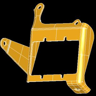
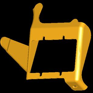
ShapeUpgrade_ShapeDivideArea can work with compounds, solids, shells and faces. During the work this tool examines each face of a specified shape and if the face area exceeds the specified maximal area, this face is divided. Face splitting is performed in the parametric space of this face. The values of splitting in U and V directions are calculated with the account of translation of the bounding box form parametric space to 3D space.

Such calculations are necessary to avoid creation of strip faces. In the process of splitting the holes on the initial face are taken into account. After the splitting all new faces are checked by area again and the splitting procedure is repeated for the faces whose area still exceeds the max allowed area. Sharing between faces in the shape is preserved and the resulting shape is of the same type as the source shape.

An example of using this tool is presented in the figures below:

Source Face
Resulting shape

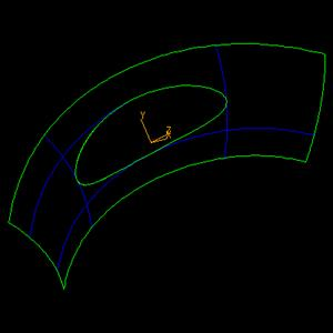
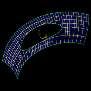
ShapeUpgrade_ShapeDivideArea is inherited from the base class ShapeUpgrade_ShapeDivide and should be used in the following way:

  • This class should be initialized on a shape with the help of the constructor or method Init() from the base class.
  • The maximal allowed area should be specified by the method MaxArea().
  • To produce a splitting use method Perform from the base class.
  • The result shape can be obtained with the help the method Result().
ShapeUpgrade_ShapeDivideArea aTool (theInputShape);
aTool.MaxArea() = theMaxArea;
aTool.Perform();
if (aTool.Status (ShapeExtend_DONE))
{
TopoDS_Shape aResultShape = aTool.Result();
ShapeFix::SameParameter (aResultShape, false);
}

Note that the use of method ShapeFix::SameParameter is necessary, otherwise the parameter edges obtained as a result of splitting can be different.

Additional methods

  • Class ShapeUpgrade_FaceDivideArea inherited from ShapeUpgrade_FaceDivide is intended for splitting a face by the maximal area criterion.
  • Class ShapeUpgrade_SplitSurfaceArea inherited from ShapeUpgrade_SplitSurface calculates the parameters of face splitting in the parametric space.

Customization of shapes

Customization tools are intended for adaptation of shape geometry in compliance with the customer needs. They modify a geometric object to another one in the shape.

To implement the necessary shape modification it is enough to initialize the appropriate tool by the shape and desirable parameters and to get the resulting shape. For example for conversion of indirect surfaces in the shape do the following:

TopoDS_Shape theInitialShape = ...;
TopoDS_Shape aResultShape = ShapeCustom::DirectFaces (theInitialShape);

Conversion of indirect surfaces

ShapeCustom::DirectFaces()
static TopoDS_Shape DirectFaces (const TopoDS_Shape& theShape);

This method provides conversion of indirect elementary surfaces (elementary surfaces with left-handed coordinate systems) in the shape into direct ones. New 2d curves (recomputed for converted surfaces) are added to the same edges being shared by both the resulting shape and the original shape S.

Shape Scaling

ShapeCustom::ScaleShape()
TopoDS_Shape ShapeCustom::ScaleShape (const TopoDS_Shape& theShape, const Standard_Real theScale);

This method returns a new shape, which is a scaled original shape with a coefficient equal to the specified value of scale. It uses the tool ShapeCustom_TrsfModification.

Conversion of curves and surfaces to BSpline

ShapeCustom_BSplineRestriction allows approximation of surfaces, curves and 2D curves with a specified degree, maximum number of segments, 2d tolerance and 3d tolerance. If the approximation result cannot be achieved with the specified continuity, the latter can be reduced.

The method with all parameters looks as follows:

ShapeCustom::BsplineRestriction()
TopoDS_Shape ShapeCustom::BSplineRestriction (const TopoDS_Shape& theShape,
const Standard_Real theTol3d, const Standard_Real theTol2d,
const Standard_Integer theMaxDegree,
const Standard_Integer theMaxNbSegment,
const GeomAbs_Shape theContinuity3d,
const GeomAbs_Shape theContinuity2d,
const Standard_Boolean theDegree,
const Standard_Boolean theRational,
const Handle(ShapeCustom_RestrictionParameters)& theParameters);

It returns a new shape with all surfaces, curves and 2D curves of BSpline/Bezier type or based on them, converted with a degree less than MaxDegree or with a number of spans less then NbMaxSegment depending on the priority parameter Degree. If this parameter is equal to True then Degree will be increased to the value GmaxDegree, otherwise NbMaxSegments will be increased to the value GmaxSegments. GmaxDegree and GMaxSegments are the maximum possible degree and the number of spans correspondingly. These values will be used in cases when an approximation with specified parameters is impossible and either GmaxDegree or GMaxSegments is selected depending on the priority.

Note that if approximation is impossible with GMaxDegree, even then the number of spans can exceed the specified GMaxSegment. Rational specifies whether Rational BSpline/Bezier should be converted into polynomial B-Spline.

Also note that the continuity of surfaces in the resulting shape can be less than the given value.

Flags

To convert other types of curves and surfaces to BSpline with required parameters it is necessary to use flags from class ShapeCustom_RestrictionParameters, which is just a container of flags. The following flags define whether a specified-type geometry has been converted to BSpline with the required parameters:

  • ConvertPlane,
  • ConvertBezierSurf,
  • ConvertRevolutionSurf,
  • ConvertExtrusionSurf,
  • ConvertOffsetSurf,
  • ConvertCurve3d – for conversion of all types of 3D curves,
  • ConvertOffsetCurv3d – for conversion of offset 3D curves,
  • ConvertCurve2d – for conversion of all types of 2D curves,
  • ConvertOffsetCurv2d – for conversion of offset 2D curves,
  • SegmentSurfaceMode – defines whether the surface would be approximated within the boundaries of the face lying on this surface.

Conversion of elementary surfaces into surfaces of revolution

ShapeCustom::ConvertToRevolution()
TopoDS_Shape ShapeCustom::ConvertToRevolution (const TopoDS_Shape& theShape);

This method returns a new shape with all elementary periodic surfaces converted to Geom_SurfaceOfRevolution. It uses the tool ShapeCustom_ConvertToRevolution.

Conversion of elementary surfaces into Bspline surfaces

ShapeCustom::ConvertToBSpline()
TopoDS_Shape ShapeCustom::ConvertToBSpline (const TopoDS_Shape& theShape,
const Standard_Boolean theExtrMode,
const Standard_Boolean theRevolMode,
const Standard_Boolean theOffsetMode);

This method returns a new shape with all surfaces of linear extrusion, revolution and offset surfaces converted according to flags to Geom_BSplineSurface (with the same parameterization). It uses the tool ShapeCustom_ConvertToBSpline.

Getting the history of modification of sub-shapes.

If, in addition to the resulting shape, you want to get the history of modification of sub-shapes you should not use the package methods described above and should use your own code instead:

  1. Create a tool that is responsible for the necessary modification.
  2. Create the tool BRepTools_Modifier that performs a specified modification in the shape.
  3. To get the history and to keep the assembly structure use the method ShapeCustom::ApplyModifier.

The general calling syntax for scaling is

TopoDS_Shape aScaledShape = ShapeCustom::ScaleShape (theShape, theScale);

Note that scale is a real value. You can refine your mapping process by using additional calls to follow shape mapping sub-shape by sub-shape. The following code along with pertinent includes can be used:

Standard_Real theScale = 100; // for example!
gp_Trsf aTrsf;
aTrsf.SetScale (gp_Pnt (0, 0, 0), theScale);
Handle(ShapeCustom_TrsfModification) aTrsfModif = new ShapeCustom_TrsfModification (aTrsf);
TopTools_DataMapOfShapeShape aContext;
BRepTools_Modifier aBRepModif;
TopoDS_Shape aRes = ShapeCustom::ApplyModifier (theShape, aTrsfModif, aContext, aBRepModif);

The map, called context in our example, contains the history. Substitutions are made one by one and all shapes are transformed. To determine what happens to a particular sub-shape, it is possible to use:

TopoDS_Shape aOneRes = aContext.Find (theOneShape);
// in case there is a doubt, you can also add:
if (aContext.IsBound (theOneShape))
{
aOneRes = aContext.Find (theOneShape);
}
// you can also sweep the entire data map:
for (TopTools_DataMapOfShapeShape::Iterator anIter (aContext); anIter.More(); anIter.Next())
{
TopoDS_Shape aOneShape = anIter.Key();
TopoDS_Shape aOneRes = anIter.Value();
}

Remove internal wires

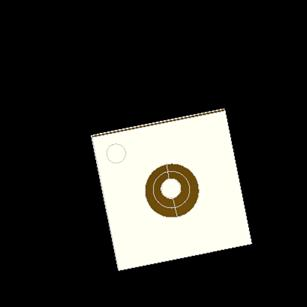
ShapeUpgrade_RemoveInternalWires tool removes internal wires with contour area less than the specified minimal area. It can work with compounds, solids, shells and faces.

If the flag RemoveFaceMode is set to TRUE, separate faces or a group of faces with outer wires, which consist only of edges that belong to the removed internal wires, are removed (seam edges are not taken into account). Such faces can be removed only for a sewed shape.

Internal wires can be removed by the methods Perform. Both methods Perform can not be carried out if the class has not been initialized by the shape. In such case the status of Perform is set to FAIL.

The method Perform without arguments removes from all faces in the specified shape internal wires whose area is less than the minimal area.

The other method Perform has a sequence of shapes as an argument. This sequence can contain faces or wires. If the sequence of shapes contains wires, only the internal wires are removed.

If the sequence of shapes contains faces, only the internal wires from these faces are removed.

  • The status of the performed operation can be obtained using method Status();
  • The resulting shape can be obtained using method GetResult().

An example of using this tool is presented in the figures below:

Source Face
Resulting shape

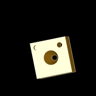
After the processing three internal wires with contour area less than the specified minimal area have been removed. One internal face has been removed. The outer wire of this face consists of the edges belonging to the removed internal wires and a seam edge. Two other internal faces have not been removed because their outer wires consist not only of edges belonging to the removed wires.

Source Face
Resulting shape

After the processing six internal wires with contour area less than the specified minimal area have been removed. Six internal faces have been removed. These faces can be united into groups of faces. Each group of faces has an outer wire consisting only of edges belonging to the removed internal wires. Such groups of faces are also removed.

The example of method application is also given below:

// initialization of the class by shape
Handle(ShapeUpgrade_RemoveInternalWires) aTool = new ShapeUpgrade_RemoveInternalWires (theInputShape);
// setting parameters
aTool->MinArea() = theMinArea;
aTool->RemoveFaceMode() = theModeRemoveFaces;
// when method Perform is carried out on separate shapes
aTool->Perform (theSeqShapes);
// when method Perform is carried out on whole shape
aTool->Perform();
// check status set after method Perform
if (aTool->Status (ShapeExtend_FAIL)
{
std::cout << "Operation failed\n";
return;
}
if (aTool->Status (ShapeExtend_DONE1))
{
const TopTools_SequenceOfShape& aRemovedWires = aTool->RemovedWires();
std::cout << aRemovedWires.Length() << " internal wires were removed\n";
}
if (aTool->Status (ShapeExtend_DONE2))
{
const TopTools_SequenceOfShape& aRemovedFaces =aTool->RemovedFaces();
std::cout << aRemovedFaces.Length() << " small faces were removed\n";
}
// getting result shape
TopoDS_Shape aRes = aTool->GetResult();

Conversion of surfaces

Class ShapeCustom_Surface allows:

  • converting BSpline and Bezier surfaces to the analytical form (using method ConvertToAnalytical());
  • converting closed B-Spline surfaces to periodic ones.(using method ConvertToPeriodic).

To convert surfaces to analytical form this class analyzes the form and the closure of the source surface and defines whether it can be approximated by analytical surface of one of the following types:

  • Geom_Plane,
  • Geom_SphericalSurface,
  • Geom_CylindricalSurface,
  • Geom_ConicalSurface,
  • Geom_ToroidalSurface.

The conversion is done only if the new (analytical) surface does not deviate from the source one more than by the given precision.

Handle(Geom_Surface) theInitSurf;
ShapeCustom_Surface aConvSurf (theInitSurf);
// conversion to analytical form
Handle(Geom_Surface) aNewSurf = aConvSurf.ConvertToAnalytical (theAllowedTol, false);
// or conversion to a periodic surface
Handle(Geom_Surface) aNewSurf = aConvSurf.ConvertToPeriodic (false);
// getting the maximum deviation of the new surface from the initial surface
Standard_Real aMaxDist = aConvSurf.Gap();

Unify Same Domain

ShapeUpgrade_UnifySameDomain tool allows unifying all possible faces and edges of a shape, which lie on the same geometry. Faces/edges are considered as 'same-domain' if the neighboring faces/edges lie on coincident surfaces/curves. Such faces/edges can be unified into one face/edge. This tool takes an input shape and returns a new one. All modifications of the initial shape are recorded during the operation.

The following options are available:

  • If the flag UnifyFaces is set to TRUE, UnifySameDomain tries to unify all possible faces;
  • If the flag UnifyEdges is set to TRUE, UnifySameDomain tries to unify all possible edges;
  • if the flag ConcatBSplines is set to TRUE, all neighboring edges, which lie on the BSpline or Bezier curves with C1 continuity on their common vertices will be merged into one common edge.

By default, UnifyFaces and UnifyEdges are set to TRUE; ConcatBSplines is set to FALSE.

The common methods of this tool are as follows:

  • Method Build() is used to unify.
  • Method Shape() is used to get the resulting shape.
  • Method Generated() is used to get a new common shape from the old shape. If a group of edges has been unified into one common edge then method Generated() called on any edge from this group will return the common edge. The same goes for the faces.

The example of the usage is given below:

// 'theSh' is the initial shape
// UnifyFaces mode on, UnifyEdges mode on, ConcatBSplines mode on
ShapeUpgrade_UnifySameDomain aTool (theSh, true, true, true);
aTool.Build();
// get the result
TopoDS_Shape aResult = aTool.Shape();
// Let theSh1 as a part of theSh
// get the new (probably unified) shape form the theSh1
TopoDS_Shape aResSh1 = aTool.Generated (theSh1);

Auxiliary tools for repairing, analysis and upgrading

Tool for rebuilding shapes

Class ShapeBuild_ReShape rebuilds a shape by making predefined substitutions on some of its components. During the first phase, it records requests to replace or remove some individual shapes. For each shape, the last given request is recorded. Requests may be applied as Oriented (i.e. only to an item with the same orientation) or not (the orientation of the replacing shape corresponds to that of the original one). Then these requests may be applied to any shape, which may contain one or more of these individual shapes.

This tool has a flag for taking the location of shapes into account (for keeping the structure of assemblies) (ModeConsiderLocation). If this mode is equal to Standard_True, the shared shapes with locations will be kept. If this mode is equal to Standard_False, some different shapes will be produced from one shape with different locations after rebuilding. By default, this mode is equal to Standard_False.

To use this tool for the reconstruction of shapes it is necessary to take the following steps:

  1. Create this tool and use method Apply() for its initialization by the initial shape. Parameter until sets the level of shape type and requests are taken into account up to this level only. Sub-shapes of the type standing beyond the line set by parameter until will not be rebuilt and no further exploration will be done.
  2. Replace or remove sub-shapes of the initial shape. Each sub-shape can be replaced by a shape of the same type or by shape containing shapes of that type only (for example, TopoDS_Edge can be replaced by TopoDS_Edge, TopoDS_Wire or TopoDS_Compound containing TopoDS_Edges). If an incompatible shape type is encountered, it is ignored and flag FAIL1 is set in Status. For a sub-shape it is recommended to use method Apply before methods Replace and Remove, because the sub-shape has already been changed for the moment by its previous modifications or modification of its sub-shape (for example TopoDS_Edge can be changed by a modification of its TopoDS_Vertex, etc.).
  3. Use method Apply for the initial shape again to get the resulting shape after all modifications have been made.
  4. Use method Apply to obtain the history of sub-shape modification.

Additional method IsNewShape can be used to check if the shape has been recorded by BRepTools_ReShape tool as a value.

Note that in fact class ShapeBuild_ReShape is an alias for class BRepTools_ReShape. They differ only in queries of statuses in the ShapeBuild_ReShape class.

Let us use the tool to get the result shape after modification of sub-shapes of the initial shape:

TopoDS_Shape theInitialShape = ...;
// creation of a rebuilding tool
Handle(ShapeBuild_ReShape) aContext = new ShapeBuild_ReShape();
// next step is optional; it can be used for keeping the assembly structure
aContext->ModeConsiderLocation = true;
// initialization of this tool by the initial shape
aContext->Apply (theInitialShape);
...
// getting the intermediate result for replacing theSubshape1 with the modified theNewSubshape1
TopoDS_Shape aTempSubshape1 = aContext->Apply (theSubshape1);
// replacing the intermediate shape obtained from theSubshape1 with the theNewSubshape1
aContext->Replace (aTempSubshape1, theNewSubshape1);
...
// for removing the sub-shape
TopoDS_Shape aTempSubshape2 = aContext->Apply (theSubshape2);
aContext->Remove (aTempSubshape2);
// getting the result and the history of modification
TopoDS_Shape aResultShape = aContext->Apply (theInitialShape);
// getting the resulting sub-shape from the theSubshape1 of the initial shape
TopoDS_Shape aResultSubshape1 = aContext->Apply (theSubshape1);

Status definition

ShapExtend_Status is used to report the status after executing some methods that can either fail, do something, or do nothing. The status is a set of flags DONEi and FAILi. Any combination of them can be set at the same time. For exploring the status, enumeration is used.

The values have the following meaning:

Value Meaning
OK, Nothing is done, everything OK
DONE1, Something was done, case 1
DONE8, Something was done, case 8
DONE, Something was done (any of DONE#)
FAIL1, The method failed, case 1
FAIL8, The method failed, case 8
FAIL The method failed (any of FAIL# occurred)

Tool representing a wire

Class ShapeExtend_WireData provides a data structure necessary to work with the wire as with an ordered list of edges, and that is required for many algorithms. The advantage of this class is that it allows to work with incorrect wires.

The object of the class ShapeExtend_WireData can be initialized by TopoDS_Wire and converted back to TopoDS_Wire.

An edge in the wire is defined by its rank number. Operations of accessing, adding and removing an edge at/to the given rank number are provided. Operations of circular permutation and reversing (both orientations of all edges and the order of edges) are provided on the whole wire as well.

This class also provides a method to check if the edge in the wire is a seam (if the wire lies on a face).

Let us remove edges from the wire and define whether it is seam edge:

TopoDS_Wire theInitWire = ...;
Handle(ShapeExtend_Wire) anExtendWire = new ShapeExtend_Wire (theInitWire);
// Removing edge theEdge1 from the wire
Standard_Integer anEdge1Index = anExtendWire->Index (theEdge1);
anExtendWire.Remove (anEdge1Index);
// Definition of whether theEdge2 is a seam edge
Standard_Integer anEdge2Index = anExtendWire->Index (theEdge2);
anExtendWire->IsSeam (anEdge2Index);

Tool for exploring shapes

Class ShapeExtend_Explorer is intended to explore shapes and convert different representations (list, sequence, compound) of complex shapes. It provides tools for:

  • obtaining the type of the shapes in the context of TopoDS_Compound,
  • exploring shapes in the context of TopoDS_Compound,
  • converting different representations of shapes (list, sequence, compound).

Tool for attaching messages to objects

Class ShapeExtend_MsgRegistrator attaches messages to objects (generic Transient or shape). The objects of this class are transmitted to the Shape Healing algorithms so that they could collect messages occurred during shape processing. Messages are added to the Maps (stored as a field) that can be used, for instance, by Data Exchange processors to attach those messages to initial file entities.

Let us send and get a message attached to object:

Handle(ShapeExtend_MsgRegistrator) aMsgReg = new ShapeExtend_MsgRegistrator();
// attaches messages to an object (shape or entity)
Message_Msg theMsg = ...;
TopoDS_Shape theShape1 = ...;
aMsgReg->Send (theShape1, theMsg, Message_WARNING);
Handle(Standard_Transient) theEnt = ...;
aMsgReg->Send (theEnt, theMsg, Message_WARNING);
// get messages attached to shape
const ShapeExtend_DataMapOfShapeListOfMsg& aMsgMap = aMsgReg->MapShape();
if (aMsgMap.IsBound (theShape1))
{
const Message_ListOfMsg& aMsgList = aMsgMap.Find (theShape1);
for (Message_ListIteratorOfListOfMsg aMsgIter (aMsgList); aMsgIter.More(); aMsgIter.Next())
{
Message_Msg aMsg = aMsgIter.Value();
}
}

Tools for performance measurement

Classes MoniTool_Timer and MoniTool_TimerSentry are used for measuring the performance of a current operation or any part of code, and provide the necessary API. Timers are used for debugging and performance optimizing purposes.

Let us try to use timers in XSDRAWIGES.cxx and IGESBRep_Reader.cxx to analyze the performance of command igesbrep:

XSDRAWIGES.cxx
...
#include <MoniTool_Timer.hxx>
#include <MoniTool_TimerSentry.hxx>
...
MoniTool_Timer::ClearTimers();
...
MoniTool_TimerSentry aTimeSentry ("IGES_LoadFile");
Standard_Integer aStatus = aReader.LoadFile (theFilePath.ToCString());
aTimeSentry.Stop();
...
MoniTool_Timer::DumpTimers (std::cout);
return;
IGESBRep_Reader.cxx
...
#include <MoniTool_TimerSentry.hxx>
...
Standard_Integer aNbEntries = theModel->NbEntities();
...
for (Standard_Integer i = 1; i<= aNbEntries; ++i)
{
MoniTool_TimerSentry aTimeSentry ("IGESToBRep_Transfer");
...
try
{
TP.Transfer (anEntry);
shape = TransferBRep::ShapeResult (theProc, anEntry);
}
...
}

The result of DumpTimer() after file translation is as follows:

TIMER Elapsed CPU User CPU Sys Hits
IGES_LoadFile 1.0 sec 0.9 sec 0.0 sec 1
IGESToBRep_Transfer 14.5 sec 4.4 sec 0.1 sec 1311

Shape Processing

Usage Workflow

The Shape Processing module allows defining and applying the general Shape Processing as a customizable sequence of Shape Healing operators. The customization is implemented via the user-editable resource file, which defines the sequence of operators to be executed and their parameters.

The Shape Processing functionality is implemented with the help of the XSAlgo interface. The main function XSAlgo_AlgoContainer::ProcessShape() does shape processing with specified tolerances and returns the resulting shape and associated information in the form of Transient.

This function is used in the following way:

TopoDS_Shape theShape = ...;
Standard_Real thePrec = ...;
Standard_Real theMaxTol = ...;
Handle(Standard_Transient) anInfo;
TopoDS_Shape aResult = XSAlgo::AlgoContainer()->ProcessShape (theShape, thePrec, theMaxTol,
"Name of ResourceFile", "NameSequence", anInfo);

Let us create a custom sequence of operations:

  1. Create a resource file with the name ResourceFile, which includes the following string:

    NameSequence.exec.op: MyOper

    where MyOper is the name of operation.

  2. Input a custom parameter for this operation in the resource file, for example:

    NameSequence.MyOper.Tolerance: 0.01

    where Tolerance is the name of the parameter and 0.01 is its value.

  3. Add the following string into void ShapeProcess_OperLibrary::Init():

    ShapeProcess::RegisterOperator (MyOper, new ShapeProcess_UOperator (myFunction));

    where myFunction is a function which implements the operation.

  4. Create this function in ShapeProcess_OperLibrary as follows:
    static bool myFunction (const Handle(ShapeProcess_Context)& theContext)
    {
    Handle(ShapeProcess_ShapeContext) aCtx = Handle(ShapeProcess_ShapeContext)::DownCast (theContext);
    if (aCtx.IsNull()) { return false; }
    TopoDS_Shape aShape = aCtx->Result();
    // receive our parameter:
    Standard_Real aToler = 0.0;
    aCtx->GetReal (Tolerance, aToler);
  5. Make the necessary operations with aShape using the received value of parameter Tolerance from the resource file.
    return true;
    }
  6. Define some operations (with their parameters) MyOper1, MyOper2, MyOper3, etc. and describe the corresponding functions in ShapeProcess_OperLibrary.
  7. Perform the required sequence using the specified name of operations and values of parameters in the resource file.

For example: input of the following string:

NameSequence.exec.op: MyOper1,MyOper3

means that the corresponding functions from ShapeProcess_OperLibrary will be performed with the original shape aShape using parameters defined for MyOper1 and MyOper3 in the resource file.

It is necessary to note that these operations will be performed step by step and the result obtained after performing the first operation will be used as the initial shape for the second operation.

Operators

DirectFaces

This operator sets all faces based on indirect surfaces, defined with left-handed coordinate systems as direct faces. This concerns surfaces defined by Axis Placement (Cylinders, etc). Such Axis Placement may be indirect, which is allowed in Cascade, but not allowed in some other systems. This operator reverses indirect placements and recomputes PCurves accordingly.

SameParameter

This operator is required after calling some other operators, according to the computations they do. Its call is explicit, so each call can be removed according to the operators, which are either called or not afterwards. This mainly concerns splitting operators that can split edges.

The operator applies the computation SameParameter which ensures that various representations of each edge (its 3d curve, the pcurve on each of the faces on which it lies) give the same 3D point for the same parameter, within a given tolerance.

  • For each edge coded as same parameter, deviation of curve representation is computed and if the edge tolerance is less than that deviation, the tolerance is increased so that it satisfies the deviation. No geometry modification, only an increase of tolerance is possible.
  • For each edge coded as not same parameter the deviation is computed as in the first case. Then an attempt is made to achieve the edge equality to same parameter by means of modification of 2d curves. If the deviation of this modified edge is less than the original deviation then this edge is returned, otherwise the original edge (with non-modified 2d curves) is returned with an increased (if necessary) tolerance. Computation is done by call to the standard algorithm BRepLib::SameParameter.

This operator can be called with the following parameters:

  • Boolean : Force (optional) – if True, encodes all edges as not same parameter then runs the computation. Else, the computation is done only for those edges already coded as not same parameter.
  • Real : Tolerance3d (optional) – if not defined, the local tolerance of each edge is taken for its own computation. Else, this parameter gives the global tolerance for the whole shape.

BSplineRestriction

This operator is used for conversion of surfaces, curves 2d curves to BSpline surfaces with a specified degree and a specified number of spans. It performs approximations on surfaces, curves and 2d curves with a specified degree, maximum number of segments, 2d tolerance, 3d tolerance. The specified continuity can be reduced if the approximation with a specified continuity was not done successfully.

This operator can be called with the following parameters:

  • Boolean : SurfaceMode allows considering the surfaces;
  • Boolean : Curve3dMode allows considering the 3d curves;
  • Boolean : Curve2dMode allows considering the 2d curves;
  • Real : Tolerance3d defines 3d tolerance to be used in computation;
  • Real : Tolerance2d defines 2d tolerance to be used when computing 2d curves;
  • GeomAbs_Shape (C0 G1 C1 G2 C2 CN) : Continuity3d is the continuity required in 2d;
  • GeomAbs_Shape (C0 G1 C1 G2 C2 CN) : Continuity2d is the continuity required in 3d;
  • Integer : RequiredDegree gives the required degree;
  • Integer : RequiredNbSegments gives the required number of segments;
  • Boolean : PreferDegree if true, RequiredDegree has a priority, else RequiredNbSegments has a priority;
  • Boolean : RationalToPolynomial serves for conversion of BSplines to polynomial form;
  • Integer : MaxDegree gives the maximum allowed Degree, if RequiredDegree cannot be reached;
  • Integer : MaxNbSegments gives the maximum allowed NbSegments, if RequiredNbSegments cannot be reached.

The following flags allow managing the conversion of special types of curves or surfaces, in addition to BSpline. They are controlled by SurfaceMode, Curve3dMode or Curve2dMode respectively; by default, only BSplines and Bezier Geometries are considered:

  • Boolean : OffsetSurfaceMode
  • Boolean : LinearExtrusionMode
  • Boolean : RevolutionMode
  • Boolean : OffsetCurve3dMode
  • Boolean : OffsetCurve2dMode
  • Boolean : PlaneMode
  • Boolean : BezierMode
  • Boolean : ConvCurve3dMode
  • Boolean : ConvCurve2dMode

For each of the Mode parameters listed above, if it is True, the specified geometry is converted to BSpline, otherwise only its basic geometry is checked and converted (if necessary) keeping the original type of geometry (revolution, offset, etc).

  • Boolean :SegmentSurfaceMode has effect only for Bsplines and Bezier surfaces. When False a surface will be replaced by a Trimmed Surface, else new geometry will be created by splitting the original Bspline or Bezier surface.

ElementaryToRevolution

This operator converts elementary periodic surfaces to SurfaceOfRevolution.

SplitAngle

This operator splits surfaces of revolution, cylindrical, toroidal, conical, spherical surfaces in the given shape so that each resulting segment covers not more than the defined number of degrees.

It can be called with the following parameters:

  • Real : Angle – the maximum allowed angle for resulting faces;
  • Real : MaxTolerance – the maximum tolerance used in computations.

SurfaceToBSpline

This operator converts some specific types of Surfaces, to BSpline (according to parameters). It can be called with the following parameters:

  • Boolean : LinearExtrusionMode allows converting surfaces of Linear Extrusion;
  • Boolean : RevolutionMode allows converting surfaces of Revolution;
  • Boolean : OffsetMode allows converting Offset Surfaces.

ToBezier

This operator is used for data supported as Bezier only and converts various types of geometries to Bezier. It can be called with the following parameters used in computation of conversion:

  • Boolean : SurfaceMode
  • Boolean : Curve3dMode
  • Boolean : Curve2dMode
  • Real : MaxTolerance
  • Boolean : SegmentSurfaceMode (default is True) has effect only for Bsplines and Bezier surfaces. When False a surface will be replaced by a Trimmed Surface, else new geometry will be created by splitting the original Bspline or Bezier surface.

The following parameters are controlled by SurfaceMode, Curve3dMode or Curve2dMode (according to the case):

  • Boolean : Line3dMode
  • Boolean : Circle3dMode
  • Boolean : Conic3dMode
  • Boolean : PlaneMode
  • Boolean : RevolutionMode
  • Boolean : ExtrusionMode
  • Boolean : BSplineMode

SplitContinuity

This operator splits a shape in order to have each geometry (surface, curve 3d, curve 2d) correspond the given criterion of continuity. It can be called with the following parameters:

  • Real : Tolerance3d
  • Integer (GeomAbs_Shape ) : CurveContinuity
  • Integer (GeomAbs_Shape ) : SurfaceContinuity
  • Real : MaxTolerance

Because of algorithmic limitations in the operator BSplineRestriction (in some particular cases, this operator can produce unexpected C0 geometry), if SplitContinuity is called, it is recommended to call it after BSplineRestriction. Continuity Values will be set as GeomAbs_Shape (i.e. C0 G1 C1 G2 C2 CN) besides direct integer values (resp. 0 1 2 3 4 5).

SplitClosedFaces

This operator splits faces, which are closed even if they are not revolutionary or cylindrical, conical, spherical, toroidal. This corresponds to BSpline or Bezier surfaces which can be closed (whether periodic or not), hence they have a seam edge. As a result, no more seam edges remain. The number of points allows to control the minimum count of faces to be produced per input closed face.

This operator can be called with the following parameters:

  • Integer : NbSplitPoints gives the number of points to use for splitting (the number of intervals produced is NbSplitPoints+1);
  • Real : CloseTolerance tolerance used to determine if a face is closed;
  • Real : MaxTolerance is used in the computation of splitting.

FixGaps

This operator must be called when FixFaceSize and/or DropSmallEdges are called. Using Surface Healing may require an additional call to BSplineRestriction to ensure that modified geometries meet the requirements for BSpline. This operators repairs geometries which contain gaps between edges in wires (always performed) or gaps on faces, controlled by parameter SurfaceMode, Gaps on Faces are fixed by using algorithms of Surface Healing. This operator can be called with the following parameters:

  • Real : Tolerance3d sets the tolerance to reach in 3d. If a gap is less than this value, it is not fixed;
  • Boolean : SurfaceMode sets the mode of fixing gaps between edges and faces (yes/no);
  • Integer : SurfaceAddSpans sets the number of spans to add to the surface in order to fix gaps;
  • GeomAbs_Shape (C0 G1 C1 G2 C2 CN) : SurfaceContinuity sets the minimal continuity of a resulting surface;
  • Integer : NbIterations sets the number of iterations;
  • Real : Beta sets the elasticity coefficient for modifying a surface [1-1000];
  • Reals : Coeff1 to Coeff6 sets energy coefficients for modifying a surface [0-10000];
  • Real : MaxDeflection sets maximal deflection of surface from an old position.

This operator may change the original geometry. In addition, it is CPU consuming, and it may fail in some cases. Also FixGaps can help only when there are gaps obtained as a result of removal of small edges that can be removed by DropSmallEdges or FixFaceSize.

FixFaceSize

This operator removes faces, which are small in all directions (spot face) or small in one direction (strip face). It can be called with the parameter Real : Tolerance, which sets the minimal dimension, which is used to consider a face, is small enough to be removed.

DropSmallEdges

This operator drops edges in a wire, and merges them with adjacent edges, when they are smaller than the given value (Tolerance3d) and when the topology allows such merging (i.e. same adjacent faces for each of the merged edges). Free (non-shared by adjacent faces) small edges can be also removed in case if they share the same vertex Parameters.

It can be called with the parameter Real : Tolerance3d, which sets the dimension used to determine if an edge is small.

FixShape

This operator may be added for fixing invalid shapes. It performs various checks and fixes, according to the modes listed hereafter. Management of a set of fixes can be performed by flags as follows:

  • if the flag for a fixing tool is set to 0 , it is not performed;
  • if set to 1 , it is performed in any case;
  • if not set, or set to -1 , for each shape to be applied on, a check is done to evaluate whether a fix is needed. The fix is performed if the check is positive.

By default, the flags are not set, the checks are carried out each individual shape.

This operator can be called with the following parameters:

  • Real : Tolerance3d sets basic tolerance used for fixing;
  • Real : MaxTolerance3d sets maximum allowed value for the resulting tolerance;
  • Real : MinTolerance3d sets minimum allowed value for the resulting tolerance.
  • Boolean : FixFreeShellMode
  • Boolean : FixFreeFaceMode
  • Boolean : FixFreeWireMode
  • Boolean : FixSameParameterMode
  • Boolean : FixSolidMode
  • Boolean : FixShellMode
  • Boolean : FixFaceMode
  • Boolean : FixWireMode
  • Boolean : FixOrientationMode
  • Boolean : FixMissingSeamMode
  • Boolean : FixSmallAreaWireMode
  • Boolean (not checked) : ModifyTopologyMode specifies the mode for modifying topology. Should be False (default) for shapes with shells and can be True for free faces.
  • Boolean (not checked) : ModifyGeometryMode specifies the mode for modifying geometry. Should be False if geometry is to be kept and True if it can be modified.
  • Boolean (not checked) : ClosedWireMode specifies the mode for wires. Should be True for wires on faces and False for free wires.
  • Boolean (not checked) : PreferencePCurveMode (not used) specifies the preference of 3d or 2d representations for an edge
  • Boolean : FixReorderMode
  • Boolean : FixSmallMode
  • Boolean : FixConnectedMode
  • Boolean : FixEdgeCurvesMode
  • Boolean : FixDegeneratedMode
  • Boolean : FixLackingMode
  • Boolean : FixSelfIntersectionMode
  • Boolean : FixGaps3dMode
  • Boolean : FixGaps2dMode
  • Boolean : FixReversed2dMode
  • Boolean : FixRemovePCurveMode
  • Boolean : FixRemoveCurve3dMode
  • Boolean : FixAddPCurveMode
  • Boolean : FixAddCurve3dMode
  • Boolean : FixSeamMode
  • Boolean : FixShiftedMode
  • Boolean : FixEdgeSameParameterMode
  • Boolean : FixSelfIntersectingEdgeMode
  • Boolean : FixIntersectingEdgesMode
  • Boolean : FixNonAdjacentIntersectingEdgesMode

SplitClosedEdges

This operator handles closed edges i.e. edges with one vertex. Such edges are not supported in some receiving systems. This operator splits topologically closed edges (i.e. edges having one vertex) into two edges. Degenerated edges and edges with a size of less than Tolerance are not processed.

Messaging mechanism

Various messages about modification, warnings and fails can be generated in the process of shape fixing or upgrade. The messaging mechanism allows generating messages, which will be sent to the chosen target medium a file or the screen. The messages may report failures and/or warnings or provide information on events such as analysis, fixing or upgrade of shapes.

Message Gravity

Enumeration Message_Gravity is used for defining message gravity. It provides the following message statuses:

  • Message_FAIL – the message reports a fail;
  • Message_WARNING – the message reports a warning;
  • Message_INFO – the message supplies information.

Tool for loading a message file into memory

Class Message_MsgFile allows defining messages by loading a custom message file into memory. It is necessary to create a custom message file before loading it into memory, as its path will be used as the argument to load it. Each message in the message file is identified by a key. The user can get the text content of the message by specifying the message key.

Format of the message file

The message file is an ASCII file, which defines a set of messages. Each line of the file must have a length of less than 255 characters. All lines in the file starting with the exclamation sign (perhaps preceded by spaces and/or tabs) are considered as comments and are ignored. A message file may contain several messages. Each message is identified by its key (string). Each line in the file starting with the dot character (perhaps preceded by spaces and/or tabs) defines the key. The key is a string starting with a symbol placed after the dot and ending with the symbol preceding the ending of the newline character \n. All lines in the file after the key and before the next keyword (and which are not comments) define the message for that key. If the message consists of several lines, the message string will contain newline symbols \n between each line (but not at the end).

The following example illustrates the structure of a message file:

!This is a sample message file
!------------------------------
!Messages for ShapeAnalysis package
!
.SampleKeyword
Your message string goes here
!
!...
!
!End of the message file

Loading the message file

A custom file can be loaded into memory using the method Message_MsgFile::LoadFile, taking as an argument the path to your file as in the example below:

Standard_CString aMsgFilePath = "(path)/sample.file";
Message_MsgFile::LoadFile (aMsgFilePath);

Tool for managing filling messages

The class Message_Msg allows using the message file loaded as a template. This class provides a tool for preparing the message, filling it with parameters, storing and outputting to the default trace file. A message is created from a key: this key identifies the message to be created in the message file. The text of the message is taken from the loaded message file (class Message_MsgFile is used). The text of the message can contain places for parameters, which are to be filled by the proper values when the message is prepared. These parameters can be of the following types:

  • string – coded in the text as %s,
  • integer – coded in the text as %d,
  • real – coded in the text as %f.

The parameter fields are filled by the message text by calling the corresponding methods AddInteger, AddReal and AddString. Both the original text of the message and the input text with substituted parameters are stored in the object. The prepared and filled message can be output to the default trace file. The text of the message (either original or filled) can be also obtained.

Message_Msg aMsg01 ("SampleKeyword");
// create the message aMsg01, identified in the file by the keyword SampleKeyword
aMsg01.AddInteger (73);
aMsg01.AddString ("SampleFile");
// fill out the code areas