|
Open CASCADE Technology 8.0.0
|

|
|
Open CASCADE Technology 8.0.0
|
|
In addition to support of exact geometrical representation of 3D objects Open CASCADE Technology provides functionality to work with tessellated representations of objects in form of meshes.
Open CASCADE Technology mesh functionality provides:
Open CASCADE Technology includes two mesh converters:
Open CASCADE also offers Advanced Mesh Products (commercial product pages, URLs may change):
Besides, we can efficiently help you in the fields of surface and volume meshing algorithms, mesh optimization algorithms etc. If you require a qualified advice about meshing algorithms, do not hesitate to benefit from the expertise of our team in that domain.
The projects dealing with numerical simulation can benefit from using SALOME - an Open Source Framework for CAE with CAD data interfaces, generic Pre- and Post- F.E. processors and API for integrating F.E. solvers.
Learn more about SALOME platform on https://www.salome-platform.org
The algorithm of shape triangulation is provided by the functionality of BRepMesh_IncrementalMesh class, which adds a triangulation of the shape to its topological data structure. This triangulation is used to visualize the shape in shaded mode.
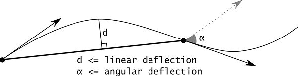
The default meshing algorithm BRepMesh_IncrementalMesh has two major options to define triangulation – linear and angular deflections.
At the first step all edges from a face are discretized according to the specified parameters.
At the second step, the faces are tessellated. Linear deflection limits the distance between a curve and its tessellation, whereas angular deflection limits the angle between subsequent segments in a polyline.
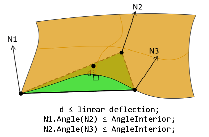
There are additional options to control behavior of the meshing of face interior: DeflectionInterior and AngleInterior. DeflectionInterior limits the distance between triangles and the face interior. AngleInterior (used for tessellation of B-spline faces only) limits the angle between normals (N1, N2 and N3 in the picture) in the nodes of every link of the triangle. There is an exception for the links along the face boundary edges, "Angular Deflection" is used for them during edges discretization.
Note that if a given value of linear deflection is less than shape tolerance then the algorithm will skip this value and will take into account the shape tolerance.
The application should provide deflection parameters to compute a satisfactory mesh. Angular deflection is relatively simple and allows using a default value (12-20 degrees). Linear deflection has an absolute meaning and the application should provide the correct value for its models. Giving small values may result in a too huge mesh (consuming a lot of memory, which results in a long computation time and slow rendering) while big values result in an ugly mesh.
For an application working in dimensions known in advance it can be reasonable to use the absolute linear deflection for all models. This provides meshes according to metrics and precision used in the application (for example, it is known that the model will be stored in meters, 0.004 m is enough for most tasks).
However, an application that imports models created in other applications may not use the same deflection for all models. Note that actually this is an abnormal situation and this application is probably just a viewer for CAD models with dimensions varying by an order of magnitude. This problem can be solved by introducing the concept of a relative linear deflection with some LOD (level of detail). The level of detail is a scale factor for absolute deflection, which is applied to model dimensions.
Meshing covers a shape with a triangular mesh. Other than hidden line removal, you can use meshing to transfer the shape to another tool: a manufacturing tool, a shading algorithm, a finite element algorithm, or a collision algorithm.
You can obtain information on the shape by first exploring it. To access triangulation of a face in the shape later, use BRep_Tool::Triangulation. To access a polygon, which is the approximation of an edge of the face, use BRep_Tool::PolygonOnTriangulation.
The main goals of the chosen architecture are:
Generally, the workflow of the component can be divided into six parts:
The component structure contains two units: IMeshData (see Data model interface) and IMeshTools, defining common interfaces for the data model and algorithmic tools correspondingly. Class IMeshTools_Context represents a connector between these units. The context class caches the data model as well as the tools corresponding to each of six stages of the workflow mentioned above and provides methods to call the corresponding tool safely (designed similarly to IntTools_Context in order to keep consistency with OCCT core tools). All stages, except for the first one, use the data model as input and perform a specific action on the entire structure. Thus, API class IMeshTools_ModelAlgo is defined in order to unify the interface of tools manipulating the data model. Each tool supposed to process the data model should inherit this interface enabling the possibility to cache it in context. In contrast to others, the model builder interface is defined by another class IMeshTools_ModelBuilder due to a different meaning of the stage. The entry point starting the entire workflow is represented by IMeshTools_MeshBuilder.
The default implementation of IMeshTools_Context is given in BRepMesh_Context class initializing the context by instances of default algorithmic tools.
The factory interface IMeshTools_MeshAlgoFactory gives the possibility to change the triangulation algorithm for a specific surface. The factory returns an instance of the triangulation algorithm via IMeshTools_MeshAlgo interface depending on the type of surface passed as parameter. It is supposed to be used at the face discretization stage.
The default implementation of AlgoFactory is given in BRepMesh_MeshAlgoFactory returning algorithms of different complexity chosen according to the passed surface type. In its turn, it is used as the initializer of BRepMesh_FaceDiscret algorithm representing the starter of face discretization stage.
Remaining interfaces describe auxiliary tools:
The data structures intended to keep discrete and temporary data required by underlying algorithms are created at the first stage of the meshing procedure. Generally, the model represents dependencies between entities of the source topological shape suitable for the target task.
Unit IMeshData provides common interfaces specifying the data model API used on different stages of the entire workflow. Dependencies and references of the designed interfaces are given in the figure below. A specific interface implementation depends on the target application which allows the developer to implement different models and use custom low-level data structures, e.g. different collections, either NCollection or STL. IMeshData_Shape is used as the base class for all data structures and tools keeping the topological shape in order to avoid possible copy-paste.
The default implementation of interfaces is given in BRepMeshData unit. The main aim of the default data model is to support discretization of edges in parallel. Curve, pcurve and other classes are therefore based on STL containers and smart pointers, which compose better with the parallel pipeline than legacy NCollection_Sequence (whose use is discouraged in new code). The model closely reflects the topology of the source shape: the number of edges in the data model is equal to the number of edges in the source model; each edge contains a set of pcurves associated with its adjacent faces, which allows creation of discrete polygons for all pcurves or the 3D curve of a particular edge in a separate thread.
Advantages: In case of necessity, the data model (probably with algorithms for its processing) can be easily substituted by another implementation supporting another kind of dependencies between elements.
An additional example of a different data model is the case when it is not required to create a mesh with discrete polygons synchronized between adjacent faces, i.e. in case of necessity to speed up creation of a rough per-face tessellation used for visualization or quick computation only (the approach used in XDEDRAW_Props).
At this stage the data model is filled by entities according to the topological structure of the source shape. A default implementation of the data model is given in BRepMeshData unit and represents the model as two sets: a set of edges and a set of faces. Each face consists of one or several wires, the first of which always represents the outer wire, while others are internal. In its turn, each wire depicts the ordered sequence of oriented edges. Each edge is characterized by a single 3D curve and zero (in case of free edge) or more 2D curves associated with faces adjacent to this edge. Both 3D and 2D curves represent a set of pairs point-parameter defined in 3D and 2D space of the reference face correspondingly. An additional difference between a curve and a pcurve is that the latter has a reference to the face it is defined for.
Model filler algorithm is represented by BRepMesh_ShapeVisitor class creating the model as a reflection to topological shape with help of BRepMesh_ShapeExplorer performing iteration over edges and faces of the target shape. Note that the algorithm operates on a common interface of the data model and creates a structure without any knowledge about the implementation details and underlying data structures. The entry point to collecting functionality is BRepMesh_ModelBuilder class.
At this stage only the edges of the data model are considered. Each edge is processed separately (with the possibility to run processing in multiple threads). The edge is checked for existing polygonal data. In case if at least one representation exists and suits the meshing parameters, it is recuperated and used as reference data for tessellation of the whole set of pcurves as well as 3D curve assigned to the edge (see BRepMesh_EdgeTessellationExtractor). Otherwise, a new tessellation algorithm is created and used to generate the initial polygon (see BRepMesh_CurveTessellator) and the edge is marked as outdated. In addition, the model edge is updated by deflection as well as recomputed same range, same parameter and degeneracy parameters. See BRepMesh_EdgeDiscret for implementation details.
IMeshData unit defines interface IMeshData_ParametersListArrayAdaptor, which is intended to adapt arbitrary data structures to the NCollection_Array1 container API. This solution is made to use both NCollection_Array1 and IMeshData_Curve as the source for BRepMesh_EdgeParameterProvider tool intended to generate a consistent parametrization taking into account the same parameter property.
In general, this stage represents a set of operations performed on the entire discrete model in order to resolve inconsistencies due to the problems caused by design, translation or rough discretization. A different sequence of operations can be performed depending on the target triangulation algorithm, e.g. there are different approaches to process self-intersections – either to amplify edges discretization by decreasing the target precision or to split links at the intersection points. At this stage the whole set of edges is considered in aggregate and their adjacency is taken into account. A default implementation of the model healer is given in BRepMesh_ModelHealer which performs the following actions:
This stage implements actions to be performed before meshing of faces. Depending on target goals it can be changed or omitted. By default, BRepMesh_ModelPreProcessor implements the functionality checking topological faces for consistency of existing triangulation, i.e.: consistency with the target deflection parameter; indices of nodes referenced by triangles do not exceed the number of nodes stored in a triangulation. If the face fails some checks, it is cleaned from triangulation and its adjacent edges are cleaned from existing polygons. This does not affect a discrete model and does not require any recomputation as the model keeps tessellations for the whole set of edges despite consistency of their polygons.
Discretization of faces is the general part of meshing algorithm. At this stage edges tessellation data obtained and processed on previous steps is used to form contours of target faces and passed as input to the triangulation algorithm. Default implementation is provided by BRepMesh_FaceDiscret class which represents a starter for triangulation algorithm. It iterates over faces available in the data model, creates an instance of the triangulation algorithm according to the type of surface associated with each face via IMeshTools_MeshAlgoFactory and executes it. Each face is processed separately, thus it is possible to process faces in a parallel mode. The class diagram of face discretization is given in the figure below.
In general, face meshing algorithms have the following structure:
BRepMesh provides user a way to switch default triangulation algorithm to a custom one, either implemented by user or available worldwide. There are three base classes that can be currently used to integrate 3rd-party algorithms:
Meshing algorithms could be provided by implementing IMeshTools_MeshAlgoFactory with related interfaces and passing it to BRepMesh_Context::SetFaceDiscret(). OCCT comes with two base 2D meshing algorithms: BRepMesh_MeshAlgoFactory (used by default) and BRepMesh_DelabellaMeshAlgoFactory.
The following example demonstrates how it could be done from Draw environment:
The code snippet below shows passing a custom mesh factory to BRepMesh_IncrementalMesh:
Range splitter tools provide functionality to generate internal surface nodes defined within the range computed using discrete model data. The base functionality is provided by BRepMesh_DefaultRangeSplitter which can be used without modifications in case of planar surface. The default splitter does not generate any internal node.
BRepMesh_ConeRangeSplitter, BRepMesh_CylinderRangeSplitter and BRepMesh_SphereRangeSplitter are specializations of the default splitter intended for quick generation of internal nodes for the corresponding type of analytical surface.
BRepMesh_UVParamRangeSplitter implements base functionality taking discretization points of face border into account for node generation. Its successors BRepMesh_TorusRangeSplitter and BRepMesh_NURBSRangeSplitter extend the base functionality for toroidal and NURBS surfaces correspondingly.
This stage implements actions to be performed after meshing of faces. Depending on target goals it can be changed or omitted. By default, BRepMesh_ModelPostProcessor commits polygonal data stored in the data model to TopoDS_Edge.