|
Open CASCADE Technology
7.4.0
|
|
|
Open CASCADE Technology
7.4.0
|
|
The IGES interface reads IGES files and translates them to Open CASCADE Technology models. The interface is able to translate one entity, a group of entities or a whole file. Before beginning a translation, you can set a range of parameters to manage the translation process. If you like, you can also check file consistency before translation. The IGES interface also translates OCCT models to IGES files.
Other kinds of data such as colors and names can be read or written with the help of XDE tools IGESCAFControl_Reader and IGESCAFControl_Writer.
Note :
This manual mainly explains how to convert an IGES file to an Open CASCADE Technology (OCCT) shape and vice versa. It provides basic documentation on conversion. For advanced information on conversion, see our E-learning & Training offerings.
IGES files produced in accordance with IGES standard versions up to and including version 5.3 can be read. IGES files that are produced by this interface conform to IGES version 5.3 (Initial Graphics Exchange Specification, IGES 5.3. ANS US PRO/IPO-100-1996).
This manual principally deals with two OCCT classes:
File translation is performed in the programming mode, via C++ calls, and the resulting OCCT objects are shapes.
All definitions in IGES version 5.3 are recognized but only 3D geometric entities are translated. When the processor encounters data, which is not translated, it ignores it and writes a message identifying the types of data, which was not handled. This message can be written either to a log file or to screen output.
Shape Healing toolkit provides tools to heal various problems, which may be encountered in translated shapes, and to make them valid in Open CASCADE. The Shape Healing is smoothly connected to IGES translator using the same API, only the names of API packages change.
You can translate an IGES file to an OCCT shape by following the steps below:
The types of IGES entities, which can be translated, are:
Note that all non-millimeter length unit values in the IGES file are converted to millimeters.
Entity attributes in the Directory Entry Section of the IGES file (such as layers, colors and thickness) are translated to Open CASCADE Technology using XDE.
Administrative data, in the Global Section of the IGES file (such as the file name, the name of the author, the date and time a model was created or last modified) is not translated to Open CASCADE Technology. Administrative data can, however, be consulted in the IGES file.
Before performing any other operation, you have to load the file using the syntax below.
The loading operation only loads the IGES file into computer memory; it does not translate it.
This step is not obligatory. Check the loaded file with:
The variable “ok is True” is returned if no fail message was found; “ok is False” is returned if there was at least one fail message.
Error messages are displayed if there are invalid or incomplete IGES entities, giving you information on the cause of the error.
If you give True, you will see fail messages only. If you give False, you will see both fail and warning messages.
Your analysis of the file can be either message-oriented or entity-oriented. Choose your preference with IFSelect_PrintCount mode = IFSelect_xxx, where xxx can be any of the following:
The following parameters can be used to translate an IGES file to an OCCT shape. If you give a value that is not within the range of possible values, it will be ignored.
manages the continuity of BSpline curves (IGES entities 106, 112 and 126) after translation to Open CASCADE Technology (Open CASCADE Technology requires that the curves in a model be at least C1 continuous; no such requirement is made by IGES).
Read this parameter with:
Modify this value with:
Default value is 1.
This parameter does not change the continuity of curves that are used in the construction of IGES BRep entities. In this case, the parameter does not influence the continuity of the resulting OCCT curves (it is ignored).
reads the precision value.
Read this parameter with:
Modify this value with:
Default value is File (0).
User defined precision value. This parameter gives the precision for shape construction when the read.precision.mode parameter value is 1. By default it is 0.0001, but can be any real positive (non null) value.
This value is in the measurement unit defined in the IGES file header.
Read this parameter with:
Modify this parameter with:
Default value is 0.0001.
The value given to this parameter is a target value that is applied to TopoDS_Vertex, TopoDS_Edge and TopoDS_Face entities. The processor does its best to reach it. Under certain circumstances, the value you give may not be attached to all of the entities concerned at the end of processing. IGES-to-OCCT translation does not improve the quality of the geometry in the original IGES file. This means that the value you enter may be impossible to attain the given quality of geometry in the IGES file.
Value of tolerance used for computation is calculated by multiplying the value of read.precision.val and the value of coefficient of transfer from the file units to millimeters.
defines the mode of applying the maximum allowed tolerance. Its possible values are:
Read this parameter with:
Modify this parameter with:
Default value is Preferred (0).
defines the maximum allowable tolerance (in mm) of the shape. It should be not less than the basis value of tolerance set in processor (either Resolution from the file or read.precision.val). Actually, the maximum between read.maxprecision.val and basis tolerance is used to define maximum allowed tolerance. Read this parameter with:
Modify this parameter with:
Default value is 1.
defines the using of BRepLib::SameParameter. Its possible values are:
preference for the computation of curves in case of 2D/3D inconsistency in an entity which has both 2D and 3D representations.
Here we are talking about entity types 141 (Boundary), 142 (CurveOnSurface) and 508 (Loop). These are entities representing a contour lying on a surface, which is translated to a TopoDS_Wire, formed by TopoDS_Edges. Each TopoDS_Edge must have a 3D curve and a 2D curve that reference the surface.
The processor also decides to re-compute either the 3D or the 2D curve even if both curves are translated successfully and seem to be correct, in case there is inconsistency between them. The processor considers that there is inconsistency if any of the following conditions is satisfied:
The parameter read.surfacecurve.mode defines which curve (3D or 2D) is used for re-computing the other one:
If no preference is defined (if the value of read.surfacecurve.mode is Default and the value of the preference flag in the entity's Parameter Data section is 0 or 3), an additional analysis is performed.
The 3D representation is preferred to the 2D in two cases:
In any other case, the 2D representation is preferred to the 3D.
If either a 3D or a 2D contour is absent in the file or cannot be translated, then it is re-computed from another contour. If the translation of both 2D and 3D contours fails, the whole curve (type 141 or 142) is not translated. If this curve is used for trimming a face, the face will be translated without this trimming and will have natural restrictions.
Read this parameter with:
Modify this value with:
Default value is Default (0).
This parameter is used within the BRepLib::EncodeRegularity() function which is called for a shape read from an IGES or a STEP file at the end of translation process. This function sets the regularity flag of an edge in a shell when this edge is shared by two faces. This flag shows the continuity, which these two faces are connected with at that edge.
Read this parameter with:
Modify this parameter with:
Default value is 0.01.
This parameter is obsolete (it is rarely used in real practice). If set to True, it affects the translation of bspline curves of degree 1 from IGES: these curves (which geometrically are polylines) are split by duplicated points, and the translator attempts to convert each of the obtained parts to a bspline of a higher continuity.
Read this parameter with:
Modify this parameter with:
Default value is Off.
These two parameters define the name of the resource file and the name of the sequence of operators (defined in that file) for Shape Processing, which is automatically performed by the IGES translator. The Shape Processing is a user-configurable step, which is performed after the translation and consists in application of a set of operators to a resulting shape. This is a very powerful tool allowing to customize the shape and to adapt it to the needs of a receiving application. By default, the sequence consists of a single operator ShapeFix that calls Shape Healing from the IGES translator.
Find an example of the resource file for IGES (which defines parameters corresponding to the sequence applied by default, i.e. if the resource file is not found) in the Open CASCADE Technology sources by the path CASROOT%/src/XSTEPResource/IGES.
IGES translator will use that file if you define the environment variable CSF_IGESDefaults, which should point to the directory where the resource file resides. Note that if you change parameter read.iges.resource.name, you should change the name of the resource file and the name of the environment variable correspondingly. The variable should contain a path to the resource file.
Default values:
This parameter defines units to which a shape should be converted when translated from IGES or STEP to CASCADE. Normally it is MM; only those applications that work internally in units other than MM should use this parameter.
Default value is MM.
A list of entities can be formed by invoking the method IGESControl_Reader::GiveList.
Several predefined operators can be used to select a list of entities of a specific type. To make a selection, use the method IGESControl_Reader::GiveList with the selection type in quotation marks as an argument. You can also make cumulative selections. For example, you would use the following syntax:
Perform translation according to what you want to translate:
Each successful translation operation outputs one shape. A series of translations gives a series of shapes. Each time you invoke TransferEntity, Transfer or Transferlist, their results are accumulated and NbShapes increases. You can clear the results (Clear function) between two translation operations, if you do not do this, the results from the next translation will be added to the accumulation. TransferRoots operations automatically clear all existing results before they start.
returns the number of shapes recorded in the result.
returns the result num, where num is an integer between 1 and NbShapes.
returns the first result in a translation operation.
returns all results in a single shape which is:
If failsonly is IFSelect_FailOnly, only fail messages will be output, if it is IFSelect_FailAndWarn, all messages will be output. Parameter “mode” can have IFSelect_xxx values where xxx can be:
NOTE that IGES entity types that are not given in the following tables are not translatable.
| IGES entity type | CASCADE shape | Comments |
|---|---|---|
| 116: Point | TopoDS_Vertex |
Curves, which form the 2D of face boundaries, are translated as Geom2D_Curves (Geom2D circles, etc.).
| IGES entity type | CASCADE shape | Comments |
|---|---|---|
| 100: Circular Arc | TopoDS_Edge | The geometrical support is a Geom_Circle or a Geom_TrimmedCurve (if the arc is not closed). |
| 102: Composite Curve | TopoDS_Wire | The resulting shape is always a TopoDS_Wire that is built from a set of TopoDS_Edges. Each TopoDS_Edge is connected to the preceding and to the following edge by a common TopoDS_Vertex. |
| 104: Conic Arc | TopoDS_Edge | The geometric support depends on whether the IGES entity's form is 0 (Geom_Circle), 1 (Geom_Ellipse), 2 (Geom_Hyperbola), or 3 (Geom_Parabola). A Geom_TrimmedCurve is output if the arc is not closed. |
| 106: Copious Data | TopoDS_Edge or TopoDS_Wire | IGES entity Copious Data (type 106, forms 1-3) is translated just as the IGES entities Linear Path (106/11-13) and the Simple Closed Planar Curve (106/63). Vectors applying to forms other than 11,12 or 63 are ignored. The Geom_BSplineCurve (geometrical support) has C0 continuity. If the Copious Data has vectors (DataType = 3) they will be ignored. |
| 110: Line | TopoDS_Edge | The supporting curve is a Geom_TrimmedCurve whose basis curve is a Geom_Line. |
| 112: Parametric Spline Curve | TopoDS_Edge or TopoDS_Wire | The geometric support is a Geom_BsplineCurve. |
| 126: BSpline Curve | TopoDS_Edge or TopoDS_Wire | |
| 130: Offset Curve | TopoDS_Edge or TopoDS_Wire | The resulting shape is a TopoDS_Edge or a TopoDS_Wire (depending on the translation of the basis curve) whose geometrical support is a Geom_OffsetCurve built from a basis Geom_Curve. Limitation: The IGES Offset Type value must be 1. |
| 141: Boundary | TopoDS_Wire | Same behavior as for the Curve On Surface (see below). The translation of a non-referenced Boundary IGES entity in a BoundedSurface IGES entity outputs a TopoDS_Edge or a TopoDS_Wire with a Geom_Curve. |
| 142: Curve On Surface | TopoDS_Wire | Each TopoDS_Edge is defined by a 3D curve and by a 2D curve that references the surface. |
The type of OCCT shapes (either TopDS_Edges or TopoDS_Wires) that result from the translation of IGES entities 106, 112 and 126 depends on the continuity of the curve in the IGES file and the value of the read.iges.bspline.continuity translation parameter.
Translation of a surface outputs either a TopoDS_Face or a TopoDS_Shell. If a TopoDS_Face is output, its geometrical support is a Geom_Surface and its outer and inner boundaries (if it has any) are TopoDS_Wires.
| IGES entity type | CASCADE shape | Comments |
|---|---|---|
| 108: Plane | TopoDS_Face | The geometrical support for the TopoDS_Face is a Geom_Plane and the orientation of its TopoDS_Wire depends on whether it is an outer TopoDS_Wire or whether it is a hole. |
| 114: Parametric Spline Surface | TopoDS_Face | The geometrical support of a TopoDS_Face is a Geom_BSplineSurface. |
| 118: Ruled Surface | TopoDS_Face or TopoDS_Shell | The translation of a Ruled Surface outputs a TopoDS_Face if the profile curves become TopoDS_Edges, or a TopoDS_Shell if the profile curves become TopoDS_Wires. Limitation: This translation cannot be completed when these two TopoDS_Wires are oriented in different directions. |
| 120: Surface Of Revolution | TopoDS_Face or TopoDS_Shell | The translation of a Surface Of Revolution outputs: a TopoDS_Face if the generatrix becomes a TopoDS_Edge, a TopoDS_Shell if the generatrix becomes a TopoDS_Wire. The geometrical support may be: Geom_CylindricalSurface, Geom_ConicalSurface, Geom_SphericalSurface, Geom_ToroidalSurface or a Geom_SurfaceOfRevolution depending on the result of the CASCADE computation (based on the generatrix type). |
| 122: Tabulated Cylinder | TopoDS_Face or TopoDS_Shell | The translation outputs a TopoDS_Face if the base becomes a TopoDS_Edge or a TopoDS_Shell if the base becomes a TopoDS_Wire. The geometrical support may be Geom_Plane, Geom_Cylindrical Surface or a Geom_SurfaceOfLinearExtrusion depending on the result of the CASCADE computation (based on the generatrix type). The Geom_Surface geometrical support is limited according to the generatrix. |
| 128: BSpline Surface | TopoDS_Face | The geometrical support of the TopoDS_Face is a Geom_BsplineSurface. |
| 140: Offset Surface | TopoDS_Face | The translation of an Offset Surface outputs a TopoDS_Face whose geometrical support is a Geom_OffsetSurface. Limitations: For OCCT algorithms, the original surface must be C1-continuous so that the Geom_OffsetSurface can be created. If the basis surface is not C1-continuous, its translation outputs a TopoDS_Shell and only the first TopoDS_Face in the TopoDS_Shell is offset. |
| 143: Bounded Surface | TopoDS_Face or TopoDS_Shell | If the basis surface outputs a TopoDS_Shell (that has more than one TopoDS_Face), the IGES boundaries are not translated. Limitations: If the bounding curves define holes, natural bounds are not created. If the orientation of the contours is wrong, it is not corrected. |
| 144: Trimmed Surface | TopoDS_Face or TopoDS_Shell | For the needs of interface processing, the basis surface must be a face. Shells are only processed if they are single-face. The contours (wires that are correctly oriented according to the definition of the IGES 142: Curve On Surface entity) are added to the face that is already created. If the orientation of the contours is wrong, it is corrected. |
| 190: Plane Surface | TopoDS_Face | This type of IGES entity can only be used in BRep entities in place of an IGES 108 type entity. The geometrical support of the face is a Geom_Plane. |
| IGES entity type | CASCADE shape | Comments |
|---|---|---|
| 186: ManifoldSolid | TopoDS_Solid | |
| 514: Shell | TopoDS_Shell | |
| 510: Face | TopoDS_Face | This is the lowest IGES entity in the BRep structure that can be specified as a starting point for translation. |
| 508: Loop | TopoDS_Wire | |
| 504: Edge List | ||
| 502: Vertex List |
| IGES entity type | CASCADE shape | Comments |
|---|---|---|
| 402/1: Associativity Instance: Group with back pointers | TopoDS_Compound | |
| 402/7: Associativity Instance: Group without back pointers | TopoDS_Compound | |
| 402/9: Associativity Instance: Single Parent | TopoDS_Face | The translation of a SingleParent entity is only performed for 402 form 9 with entities 108/1 and 108/-1. The geometrical support for the TopoDS_Face is a Geom_Plane with boundaries: the parent plane defines the outer boundary; the child planes define the inner boundaries. |
| IGES entity type | CASCADE shape | Comments |
|---|---|---|
| 308: Subfigure Definition | TopoDS_Compound | This IGES entity is only translated when there are no Singular Subfigure Instance entities. |
| 408: Singular Subfigure Instance | TopoDS_Compound | This shape has the Subfigure Definition Compound as its origin and is positioned in space by its translation vector and its scale factor. |
| IGES entity type | CASCADE shape | Comments |
|---|---|---|
| 124: Transformation Matrix | Geom_Transformation | This entity is never translated alone. It must be included in the definition of another entity. |
Messages are displayed concerning the normal functioning of the processor (transfer, loading, etc.). You must declare an include file:
You have the choice of the following options for messages:
level modifies the level of messages:
During the transfer of IGES to Open CASCADE Technology several parameters are used as tolerances and precisions for different algorithms. Some of them are computed from other using specific functions.
Transfer starts from one entity treated as a root (either the actual root in the IGES file or an entity selected by the user). The function which performs the transfer (that is IGESToBRep_Actor::Transfer or IGESToBRep_Reader::Transfer) creates an object of the type IGESToBRep_CurveAndSurface, which is intended for translating geometry.
This object contains three tolerances: Epsilon, EpsGeom and EpsCoeff.
Parameter Epsilon is set by default to value 10-4. In most cases when it is used in the package IGESToBRep, it is reset to a fixed value, either 10-5 or 10-4 or 10-3. It is used as precision when comparing angles and transformation matrices and does not have influence on the tolerance of the resulting shape.
Parameter EpsGeom is set right after creating a IGESToBRep_CurveAndSurface object to the value of resolution, taken either from the Global section of an IGES file, or from the XSTEP.readprecision.val parameter, depending on the value of XSTEP.readprecision.mode.
Parameter EpsCoeff is set by default to 10-6 and is not changed.
During the transfer of a shape, new objects of type IGESToBRep_CurveAndSurface are created for translating subshapes. All of them have the same tolerances as the root object.
Geometrical entities are translated by classes IGESToBRep_BasicCurve and IGESToBRep_BasicSurface. Methods of these classes convert curves and surfaces of an IGES file to Open CASCADE Technology geometry objects: Geom_Curve, Geom_Surface, and Geom_Transformation.
Since these objects are not BRep objects, they do not have tolerances. Hence, tolerance parameters are used in these classes only as precisions: to detect specific cases (e.g., to distinguish a circle, an ellipse, a parabola and a hyperbola) and to detect bad cases (such as coincident points).
Use of precision parameters is reflected in the following classes:
IGES entities represented as topological shapes and geometrical objects are translated into OCCT shapes by use of the classes IGESToBRep_TopoCurve, IGESToBRep_TopoSurface, IGESToBRep_BRepEntity and ShapeFix_Wire.
Class IGESToBRep_BRepEntity is intended for transferring BRep entities (IGES version is 5.1 or greater) while the two former are used for translating geometry and topology defined in IGES versions prior to 5.1. Methods from IGESToBRep_BRepEntity call methods from IGESToBRep_TopoCurve and IGESToBRep_TopoSurface, while those call methods from IGESToBRep_BasicCurve and IGESToBRep_BasicSurface to translate IGES geometry into OCCT geometry.
Although the IGES file contains only one parameter for tolerance in the Global Section, OCCT shapes are produced with different tolerances. As a rule, updating the tolerance is fulfilled according to local distances between shapes (distance between vertices of adjacent edges, deviation of edge’s 3D curve and its parametric curve and so on) and may be less or greater than precision in the file.
The following classes show what default tolerances are used when creating shapes and how they are updated during transfer.
All methods are in charge of transferring curves from IGES curve entities (TransferCompositeCurve, Transfer2dCompositeCurve, TransferCurveOnFace, TransferBoundaryOnFace, TransferOffsetCurve, TransferTopoBasicCurve) if an entity has transformation call to IGESData_ToolLocation::ConvertLocation with Epsilon value set to 10-4.
All faces created by this class have tolerance Precision::Confusion.
After performing a simple mapping, shape-healing algorithms are called (class ShapeFix_Shape) by IGESToBRep_Actor::Transfer(). Shape-healing algorithm performs the correction of the resulting OCCT shape. Class ShapeFix_Wire can increase the tolerance of a shape. This class is used in IGESToBRep_BRepEntity::TransferLoop, IGESToBRep_TopoCurve::TransferBoundaryOnFace and IGESToBRep_TopoCurve::TransferCurveOnFace for correcting a wire. The maximum possible tolerance applied to the edges or vertices after invoking the methods of this class is MaxTolerance (set by method ShapeFix_Wire::MaxTolerance() ).
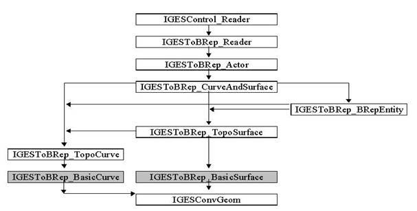
The following diagram illustrates the structure of calls in reading IGES. The highlighted classes produce OCCT geometry.
You can translate OCCT shapes to IGES entities in the following steps:
You can translate several shapes before writing a file. Each shape will be a root entity in the IGES model.
There are two families of OCCT objects that can be translated:
Choose the unit and the mode you want to use to write the output file as follows:
The following parameters are used for the OCCT-to-IGES translation.
Read this parameter with:
Modify this parameter with:
Default value is 0.0001.
and
are the same as the corresponding read.iges.* parameters. Note that the default sequence for writing contains DirectFaces operator, which converts elementary surfaces based on left-hand axes (valid in CASCADE) to right-hand axes (which are valid only in IGES).
Default values :
You can perform the translation in one or several operations. Here is how you translate topological and geometrical objects:
ok is True if translation was correctly performed and False if there was at least one entity that was not translated.
where geom is Handle(Geom_Curve) or Handle(Geom_Surface); ok is True if the translation was correctly performed and False if there was at least one entity whose geometry was not among the allowed types.
Write the IGES file with:
to give the file name.
where S is Standard_OStream ok is True if the operation was correctly performed and False if an error occurred (for instance, if the processor could not create the file).
Translated objects depend on the write mode that you chose. If you chose the Face mode, all of the shapes are translated, but the level of topological entities becomes lower (geometrical one). If you chose the BRep mode, topological OCCT shapes become topological IGES entities.
| CASCADE shape | IGES entity type | Comments |
|---|---|---|
| Geom_BsplineCurve | 126: BSpline Curve | |
| Geom_BezierCurve | 126: BSpline Curve | |
| Geom_TrimmedCurve | All types of translatable IGES curves | The type of entity output depends on the type of the basis curve. If the curve is not trimmed, limiting points will be defined by the CASCADE RealLast value. |
| Geom_Circle | 100: Circular Arc or 126: BSpline Curve | A BSpline Curve is output if the Geom_Circle is closed |
| Geom_Ellipse | 104: Conic Arc or 126: BSpline Curve | A Conic Arc has Form 1. A BSpline Curve is output if the Geom_Ellipse is closed. |
| Geom_Hyperbola | 104: Conic Arc | Form 2 |
| Geom_Parabola | 104: Conic Arc | Form 3 |
| Geom_Line | 110: Line | |
| Geom_OffsetCurve | 130: Offset Curve |
| CASCADE shapes | IGES entity type | Comments |
|---|---|---|
| Geom_BSplineSurface | 128: BSpline Surface | |
| Geom_BezierSurface | 128: BSpline Surface | |
| Geom_RectangularTrimmedSurface | All types of translatable IGES surfaces. | The type of entity output depends on the type of the basis surface. If the surface is not trimmed and has infinite edges/sides, the coordinates of the sides in IGES will be limited to the CASCADE RealLast value. |
| Geom_Plane | 128: BSpline Surface or 190: Plane Surface | A BSpline Surface (of degree 1 in U and V) is output if you are working in the face mode. A Plane Surface is output if you are working in the BRep mode. |
| Geom_CylindricalSurface | 120: Surface Of Revolution | |
| Geom_ConicalSurface | 120: Surface Of Revolution | |
| Geom_SphericalSurface | 120: Surface Of Revolution | |
| Geom_ToroidalSurface | 120: Surface Of Revolution | |
| Geom_SurfaceOfLinearExtrusion | 122: Tabulated Cylinder | |
| Geom_SurfaceOfRevolution | 120: Surface Of Revolution | |
| Geom_OffsetSurface | 140: Offset Surface |
| CASCADE shapes | IGES entity type | Comments |
|---|---|---|
| Single TopoDS_Vertex | 116: 3D Point | |
| TopoDS_Vertex in a TopoDS_Edge | No equivalent | Not transferred. |
| TopoDS_Edge | All types of translatable IGES curves | The output IGES curve will be the one that corresponds to the Open CASCADE Technology definition. |
| Single TopoDS_Wire | 102: Composite Curve | Each TopoDS_Edge in the TopoDS_Wire results in a curve. |
| TopoDS_Wire in a TopoDS_Face | 142: Curve On Surface | Both curves (3D and pcurve) are transferred if they are defined and result in a simple curve or a composite curve depending on whether there is one or more edges in the wire.Note: if the basis surface is a plane (108), only the 3D curve is used. |
| TopoDS_Face | 144: Trimmed Surface | |
| TopoDS_Shell | 402: Form 1 Group or no equivalent | Group is created only if TopoDS_Shell contains more than one TopoDS_Face. The IGES group contains Trimmed Surfaces. |
| TopoDS_Solid | 402: Form 1 Group or no equivalent | Group is created only if TopoDS_Solid contains more than one TopoDS_Shell. One IGES entity is created per TopoDS_Shell. |
| TopoDS_CompSolid | 402: Form 1 Group or no equivalent | Group is created only if TopoDS_CompSolid contains more than one TopoDS_Solid. One IGES entity is created per TopoDS_Solid. |
| TopoDS_Compound | 402: Form 1 Group or no equivalent | Group is created only if TopoDS_Compound contains more than one item. One IGES entity is created per TopoDS_Shape in the TopoDS_Compound. If TopoDS_Compound is nested into another TopoDS_Compound, it is not mapped. |
| CASCADE shapes | IGES entity type | Comments |
|---|---|---|
| Single TopoDS_Vertex | No equivalent | Not transferred. |
| TopoDS_Vertex in a TopoDS_Edge | One item in a 502: VertexList | |
| TopoDS_Edge | No equivalent | Not transferred as such. This entity serves as a part of a Loop entity. |
| TopoDS_Edge in a TopoDS_Wire | One item in a 504: EdgeList | |
| TopoDS_Wire | 508: Loop | |
| TopoDS_Face | 510: Face | If the geometrical support of the face is a plane, it will be translated as a 190 entity PlaneSurface. |
| TopoDS_Shell | 514: Shell | |
| TopoDS_Solid | 186: Manifold Solid | |
| TopoDS_CompSolid | 402 Form1 Group or no equivalent | Group is created only if TopoDS_Compound contains more than one item. One IGES Manifold Solid is created for each TopoDS_Solid in the TopoDS_CompSolid. |
| TopoDS_Compound | 402 Form1 Group or no equivalent | Group is created only if TopoDS_Compound contains more than one item. One IGES entity is created per TopoDS_Shape in the TopoDS_Compound. If TopoDS_Compound is nested into another TopoDS_Compound it is not mapped. |
There are several possibilities to set resolution in an IGES file. They are controlled by write.precision.mode parameter; the dependence between the value of this parameter and the set resolution is described in paragraph Setting the translation parameters.
If the value of parameter write.precision.mode is -1, 0 or 1, resolution is computed from tolerances of sub-shapes inside the shape to be translated. In this computation, only tolerances of TopoDS_Edges and TopoDS_Vertices participate since they reflect the accuracy of the shape. TopoDS_Faces are ignored in computations since their tolerances may have influence on resulting computed resolution while IGES resolution mainly concerns points and curves but not surfaces.
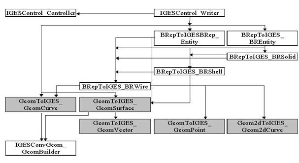
The following diagram illustrates the class structure in writing IGES. The highlighted classes are intended to translate geometry.
XSTEPDRAW UL is intended for creating executables for testing XSTEP interfaces interactively in the DRAW environment. It provides an additional set of DRAW commands specific for the data exchange tasks, which allow loading and writing data files and analysis of resulting data structures and shapes.
In the description of commands, square brackets ([]) are used to indicate optional parameters. Parameters given in the angle brackets (<>) and sharps (#) are to be substituted by an appropriate value. When several exclusive variants are possible, vertical dash (|) is used.
A set of parameters for importing and exporting IGES files is defined in the XSTEP resource file. In XSTEPDRAW, these parameters can be viewed or changed using command
Command param with no arguments gives a list of all parameters with their values. When argument parameter_name is specified, information about this parameter is printed (current value and short description).
The third argument is used to set a new value of the given parameter. The result of the setting is printed immediately.
During all interface operations, the protocol of the process (fail and warning messages, mapping of the loaded entities into OCCT shapes etc.) can be output to the trace file. Two parameters are defined in the DRAW session: trace level (integer value from 0 to 9, default is 0), and trace file (default is a standard output).
Command xtrace is intended to view and change these parameters:
For a description of parameters used in reading an IGES file refer to Setting the translation parameters.
These parameters are set by command param :
| Description | Name | Values |
|---|---|---|
| Precision for input entities | read.precision.mode | 0 or 1 |
| read.precision.val | real | |
| Continuity of B splines | read.iges.bspline.continuity | 0-2 |
| Surface curves | read.surfacecurve.mode | 2, 3 or 0 |
It is possible either only to load an IGES file into memory (i.e. to fill the model with data from the file), or to read it (i.e. to load and convert all entities to OCCT shapes).
Loading is done by the command
Once the file is loaded, it is possible to investigate the structure of the loaded data. To learn how to do it see Analyzing the transferred.
Reading of an IGES file is done by the command
Here a dot can be used instead of a filename if the file is already loaded by xload or igesbrep command. In that case, only conversion of IGES entities to OCCT shapes will be done.
Command igesbrep will interactively ask the user to select a set of entities to be converted:
| N | Mode | Description |
|---|---|---|
| 0 | End | finish conversion and exit igesbrep |
| 1 | Visible roots | convert only visible roots |
| 2 | All roots | convert all roots |
| 3 | One entity | convert entity with number provided by the user |
| 4 | Selection | convert only entities contained in selection |
After the selected set of entities is loaded the user will be asked how loaded entities should be converted into OCCT shapes (e.g., one shape per root or one shape for all the entities). It is also possible to save loaded shapes in files, and to cancel loading.
The second parameter of the igesbrep command defines the name of the loaded shape. If several shapes are created, they will get indexed names. For instance, if the last parameter is ‘s’, they will be s_1, ... s_N.
<selection> specifies the scope of selected entities in the model, it is xst-transferrable-roots by default. An asterisk “*” can be specified instead of iges-visible-transf-roots. For possible values of selection refer to Selecting entities section.
Instead of igesbrep it is possible to use commands:
which outputs the result of translation of each selected entity into one shape, or
which outputs the result of translation of all selected entities into one shape (TopoDS_Compound for several entities).
An asterisk “*” can be specified instead of selection, it means xst-transferrable-roots.
During the IGES translation, a map of correspondence between IGES entities and OCCT shapes is created. The following commands are available:
The procedure of analysis of the data import can be divided into two stages:
General statistics on the loaded data can be obtained by using command
The information printed by this command depends on the symbol specified:
| Symbol | Output |
|---|---|
| g | Prints information contained in the header of the file (Start and Global sections) |
| c or f | Runs check procedure of the integrity of the loaded data and prints the resulting statistics (f works only with fails while c with both fail and warning messages) |
| t | The same as c or f, with a list of failed or warned entities |
| m or l | The same as t but also prints a status for each entity |
| e | Lists all entities of the model with their numbers, types, status of validity etc. |
| r | The same as e but lists only root entities |
There is a set of special objects, which can be used to operate with the loaded model. They can be of the following types:
| Special object type | Operation |
|---|---|
| Selection Filters | allow selecting subsets of entities of the loaded model |
| Counters | Calculate statistics on the model data |
A list of these objects defined in the current session can be printed in DRAW by command
In the following commands if several <selection> arguments are specified the results of each following selection are applied to the results of the previous one.
prints a list of loaded entities defined by selection argument.
prints a number of loaded entities defined by selection argument.
Three commands are used to calculate statistics on the entities in the model:
Optional <selection> argument, if specified, defines a subset of entities, which are to be taken into account. Argument <counter> should be one of the currently defined counters:
| Counter | Operation |
|---|---|
| xst-types | Calculates how much entities of each OCCT type exist |
| iges-types | Calculates how much entities of each IGES type and form exist |
| iges-levels | Calculates how much entities lie in different IGES levels |
The command:
gives a list of entity types which were encountered in the last loaded file (with a number of IGES entities of each type). The list can be shown not for all entities but for a subset of them. This subset is defined by an optional selection argument.
Entities in the IGES file are numbered in the succeeding order. An entity can be identified either by its number (#) or by its label. Label is the letter ‘D’ followed by the index of the first line with the data for this entity in the Directory Entry section of the IGES file. The label can be calculated on the basis of the number as ‘D(2*# -1)’. For example, entity # 6 has label D11.
All of the following commands are available only after the data are converted into OCCT shapes (i.e. after command igesbrep).
provides all statistics on the last transfer, including the list of transferred entities with mapping from IGES to OCCT types, as well as fail and warning messages. The parameter <symbol> defines what information will be printed:
The sign ‘*’ before the parameters n, s, b, t, r makes it work on all entities (not only on roots). The sign ‘?’ before n, s, b, t limits the scope of information to invalid entities.
Optional argument <selection> can limit the action of the command with a selected subset of entities. To get help, run this command without arguments.
For example, to get translation ratio on IGES faces, you can use.
The second version of the same command is TPSTAT (not capital spelling).
Symbol can be of the following values:
Sometimes the trimming contours of IGES faces (i.e., entity 141 for 143, 142 for 144) can be lost during translation due to fails.
The number of lost trims and the corresponding IGES entities can be obtained by the command:
It outputs the rank and DE numbers of faces that lost their trims and their numbers for each type (143, 144, 510) and their total number. If a face lost several of its trims it is output only once.
Optional parameter <IGES_type> can be TrimmedSurface, BoundedSurface or Face to specify the only type of IGES faces.
For example, to get untrimmed 144 entities, use command
To get the information on OCCT shape contents, use command
It outputs the number of each kind of shapes (vertex, edge, wire, etc.) in a shape and some geometrical data (number of C0 surfaces, curves, indirect surfaces, etc.).
Note. The number of faces is returned as a number of references. To obtain the number of single instances the standard command (from TTOPOLOGY executable) nbshapes can be used.
To analyze the internal validity of a shape, use command
It checks the geometry and topology of a shape for different cases of inconsistency, like self-intersecting wires or wrong orientation of trimming contours. If an error is found, it copies bad parts of the shape with the names "expurged_subshape_name _#" and generates an appropriate message. If possible, this command also tries to find IGES entities the OCCT shape was produced from.
<expurged_shape_name> will contain the original shape without invalid subshapes.
To get information on tolerances of subshapes, use command
It outputs maximum, average and minimum values of tolerances for each kind of subshapes having tolerances or it can output tolerances of all subshapes of the whole shape.
When specifying min and max arguments this command outputs shapes with names <shape_name>... and their total number with tolerances in the range [min, max].
<Symbol> is used for specifying the kind of sub-shapes to analyze:
Refer to Setting the translation parameters for a description of parameters used in reading an IGES file. The parameters are set by command param:
| Description | Name | Values |
|---|---|---|
| Author | XSTEP.iges.header.author | String |
| Company | XSTEP.iges.header.company | String |
| Receiver | XSTEP.iges.header.receiver | String |
| Write mode for shapes | XSTEP.iges.writebrep.mode | 0/Faces or 1/BRep |
| Measurement units | XSTEP.iges.unit | 1-11 (or a string value) |
Several shapes can be written in one file. To start writing a new file, enter command
This command clears the InterfaceModel to make it empty.
Converts the specified shapes into IGES entities and puts them into the InterfaceModel.
Allows writing the prepared model to a file with name filename.igs.
Before performing any other operation, you must load an IGES file with:
Loading the file only memorizes, but does not translate the data.
This step is not obligatory. See the description of Checking the IGES file above.
See the description of Setting translation parameters above.
In addition, the following parameters can be set for XDE translation of attributes:
The following function performs a translation of the whole document:
where doc is a variable which contains a handle to the output document and should have a type Handle(TDocStd_Document).
The translation from XDE to IGES can be initialized as follows:
The following parameters can be set for translation of attributes to IGES:
You can perform the translation of a document by calling the function:
where "doc" is a variable which contains a handle to the input document for transferring and should have a type Handle(TDocStd_Document).
Write an IGES file with:
or
where S is OStream.
 1.8.13