

Sat, 11/22/2025 - 01:30
Forums:
I'm trying to make a conical surface bounded by two lines and a circular arc. Here is a sample code
double h = 20.0;
double a = 60.0 * (M_PI / 180.0);
double dh = h * tan(a / 1.0);
double r = dh;

gp_Dir aDir(0.0, 0.0, 1.0);

gp_Pnt aPnt0(0.0,           0,              0.0          );
gp_Pnt aPnt1(dh,            0,              aPnt0.Z() + h);
gp_Pnt aPnt2(0,             dh,             aPnt0.Z() + h);

//
gp_Circ circ(gp_Ax2(gp_Pnt(0.0, 0.0, aPnt0.Z() + h), aDir, gp_Dir(1.0, 0.0, 0.0)), r);
Handle(Geom_TrimmedCurve) aArc = GC_MakeArcOfCircle(circ, aPnt1, aPnt2, true);
Handle(Geom_TrimmedCurve) aSeg0 = GC_MakeSegment(aPnt0, aPnt1);
Handle(Geom_TrimmedCurve) aSeg1 = GC_MakeSegment(aPnt2, aPnt0);
// Wire
TopoDS_Edge anEdge1 = BRepBuilderAPI_MakeEdge(aSeg0);
TopoDS_Edge anEdge2 = BRepBuilderAPI_MakeEdge(aArc);
TopoDS_Edge anEdge3 = BRepBuilderAPI_MakeEdge(aSeg1);
TopoDS_Wire aWire  = BRepBuilderAPI_MakeWire(anEdge1, anEdge2, anEdge3);
// Surface
GC_MakeConicalSurface coneMaker(gp_Ax2(aPnt0, aDir, gp_Dir(1.0, 0.0, 0.0)), a, 0.0);
Handle(Geom_ConicalSurface) aCone = coneMaker.Value();
// Face
BRep_Builder B;
B.MakeFace(m_Shape, aCone, 0.001);
BRepLib_MakeFace faceMaker(m_Shape);
faceMaker.Add(aWire);
m_Shape = faceMaker.Face();
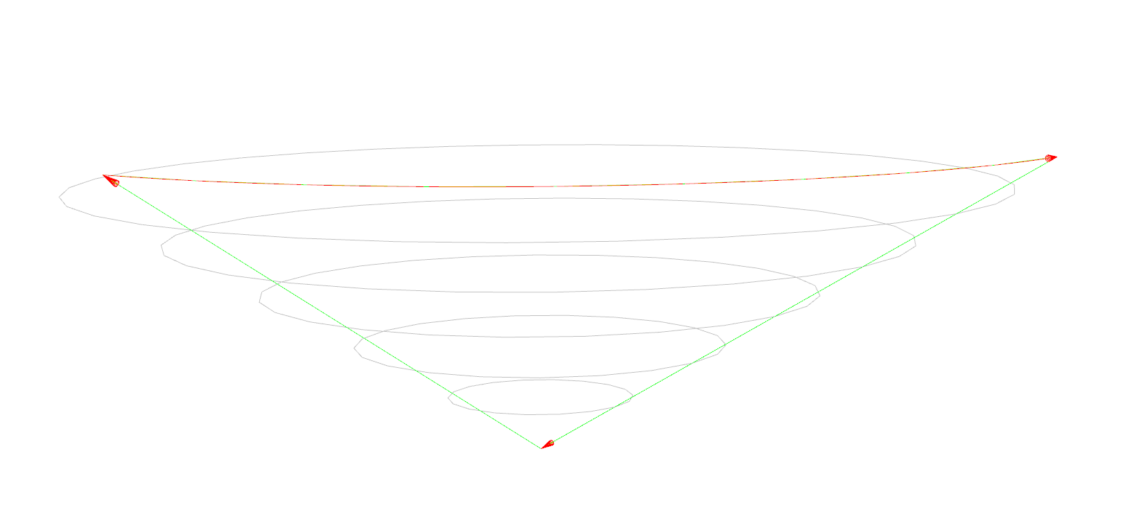
Result of rendering this m_Shape shown in the first attached screenshot.
Adding
Handle(ShapeFix_Face) aFixShape = new ShapeFix_Face(m_Shape);
if (aFixShape->Perform())
{
    m_Shape = aFixShape->Face();
}
does not help much. See the second screenshot.
What am I doing wrong?
P.S. Green lines with arrows are just my visualization of the edges.
Attachments:
Sat, 11/22/2025 - 01:47
Hello, the topology is not valid. The wire need to organise circle and also you need to add 2d curve (pcurve, 2d curve, seam edge).
The most comfortable example with demo: https://dev.opencascade.org/content/sample-cylinder-order-edges-wire
Related ticket: https://dev.opencascade.org/content/creating-face-cylindrical-surface
Working sample: https://dev.opencascade.org/content/splitting-edge-cylinder
My overall recommendation - try to work with OCCT's Draw command and play with topology and geometry to get the understanding of the topology.
Best regards, Dmitrii.
Tue, 11/25/2025 - 06:37
How to correctly update the pcurve curve of the seamEdge on the side face of a cylinder? In a cylindrical surface, the seamEdge consists of two topological edges that are IsSame. How should the pcurve curves of these two seamEdges be updated to ensure they are correctly projected onto the cylindrical surface? Looking forward to your reply.
void BRep_CAD_View::UpdateEdgeOnCylinderPcurve(TopoDS_Edge& newEdge, TopoDS_Edge& oldEdge, TopoDS_Face& face)
{
TopLoc_Location locF;
Handle(Geom_Surface) surf = BRep_Tool::Surface(face, locF);
if (surf.IsNull()) return;
// 1) 先从 oldSeam 上取一条 pcurve,得到它的 u0(角度参数)
Standard_Real f2dOld, l2dOld;
Handle(Geom2d_Curve) c2dOld =
BRep_Tool::CurveOnSurface(oldEdge, face, f2dOld, l2dOld);
if (c2dOld.IsNull()) return;
Standard_Real tMidOld = 0.5 * (f2dOld + l2dOld);
gp_Pnt2d uvMidOld = c2dOld->Value(tMidOld);
Standard_Real u0 = uvMidOld.X(); // 这条 seam 对应的固定 U
// 2) 取 newSeam 的两个顶点,在 surface 上求 (u,v),我们只要 v,用旧的 u0
TopoDS_Vertex v1 = TopExp::FirstVertex(newEdge, Standard_True);
TopoDS_Vertex v2 = TopExp::LastVertex(newEdge, Standard_True);
gp_Pnt P1 = BRep_Tool::Pnt(v1);
gp_Pnt P2 = BRep_Tool::Pnt(v2);
// 注意坐标系:face 可能带 Location,这里变换到曲面局部坐标系
gp_Trsf trInv = locF.Transformation().Inverted();
P1.Transform(trInv);
P2.Transform(trInv);
GeomAPI_ProjectPointOnSurf proj1(P1, surf);
GeomAPI_ProjectPointOnSurf proj2(P2, surf);
Standard_Real uu1, vv1, uu2, vv2;
proj1.LowerDistanceParameters(uu1, vv1);
proj2.LowerDistanceParameters(uu2, vv2);
// 强制使用 old seam 的 u0,v 用新端点的
gp_Pnt2d uv1(u0, vv1);
gp_Pnt2d uv2(u0, vv2);
// 3) 在 UV 平面上做一条线段当作 newSeam 的 pcurve
Handle(Geom2d_TrimmedCurve) pcNew = GCE2d_MakeSegment(uv1, uv2);
Handle(Geom2d_Curve) pcRight;
if (u0 == 0.)
{
pcRight = Handle(Geom2d_Curve)::DownCast(pcNew->Copy());
gp_Trsf2d tr2d;
tr2d.SetTranslation(gp_Vec2d(2.0 * M_PI, 0.0));
pcRight->Transform(tr2d);
}
else if (u0 == 2.0 * M_PI)
{
pcRight = Handle(Geom2d_Curve)::DownCast(pcNew->Copy());
gp_Trsf2d tr2d;
tr2d.SetTranslation(gp_Vec2d(-2.0 * M_PI, 0.0));
pcRight->Transform(tr2d);
}
BRep_Builder B;
B.UpdateEdge(newEdge, pcNew, pcRight, surf, locF, Precision::Confusion());
// 4) 更新顶点在这条 pcurve 上的参数
Geom2dAPI_ProjectPointOnCurve projPC1(uv1, pcNew);
Geom2dAPI_ProjectPointOnCurve projPC2(uv2, pcNew);
Standard_Real par1 = projPC1.LowerDistanceParameter();
Standard_Real par2 = projPC2.LowerDistanceParameter();
B.UpdateVertex(v1, par1, newEdge, surf, locF, Precision::Confusion());
B.UpdateVertex(v2, par2, newEdge, surf, locF, Precision::Confusion());
}
Sat, 11/22/2025 - 03:35
Thanks for the quick reply. My wire does form a circle: line (p0, p1), an arc (p1, p2), and the second line (p2, p0). As for the pcurves - my bad, it is not my real code, just a code snippet where I'm trying to understand issues I have with cones. I modified the code to add pcurves to each edge using projection (should be enough for the POC), like this:
And the same for the two other edges. I have also set the wire orientation to
TopAbs_REVERSED. Now the code is rendered, and it shows the same issue I have in my main code - the pure quality of the cone, shown in the screenshots.