

Tue, 07/11/2017 - 19:57
Hello everyone,
I have been struggling with a very basic task for quite a while. I would like to import a STEP file such as the one from here https://github.com/stepcode/stepcode/blob/master/data/ap214e3/as1-oc-214.stp, triangulate each of its parts and save it in a separate STL file.
Minimal (not really) Working Example:
Handle(TDocStd_Document) doc;
Handle(XCAFApp_Application) anApp = XCAFApp_Application::GetApplication();
anApp->NewDocument(filename,doc);
STEPCAFControl_Reader reader;
reader.ReadFile(filename);
reader.Transfer(doc);
Handle(XCAFDoc_ShapeTool) myAssembly = XCAFDoc_DocumentTool::ShapeTool(doc->Main());
TDF_LabelSequence FreeShapes;
myAssembly->GetFreeShapes(FreeShapes);
TDF_LabelSequence shapes;
myAssembly->GetComponents(FreeShapes.Value(1),shapes,true);
for(Standard_Integer i=1; i<=shapes.Length(); ++i)
{
TDF_Label label = shapes.Value(i);
TopoDS_Shape shape;
myAssembly->GetShape(label,shape);
TopAbs_ShapeEnum type = shape.ShapeType();
if(type!=0)
{
BRepMesh_IncrementalMesh BMesh(shape,0.1,Standard_True);
StlAPI_Writer STLwriter;
// For the sake of the MWE simply i.stl.
std::stringstream stream;
stream << i;
std::string filename;
stream >> filename;
filename += ".stl";
STLwriter.Write(shape,filename.c_str());
}
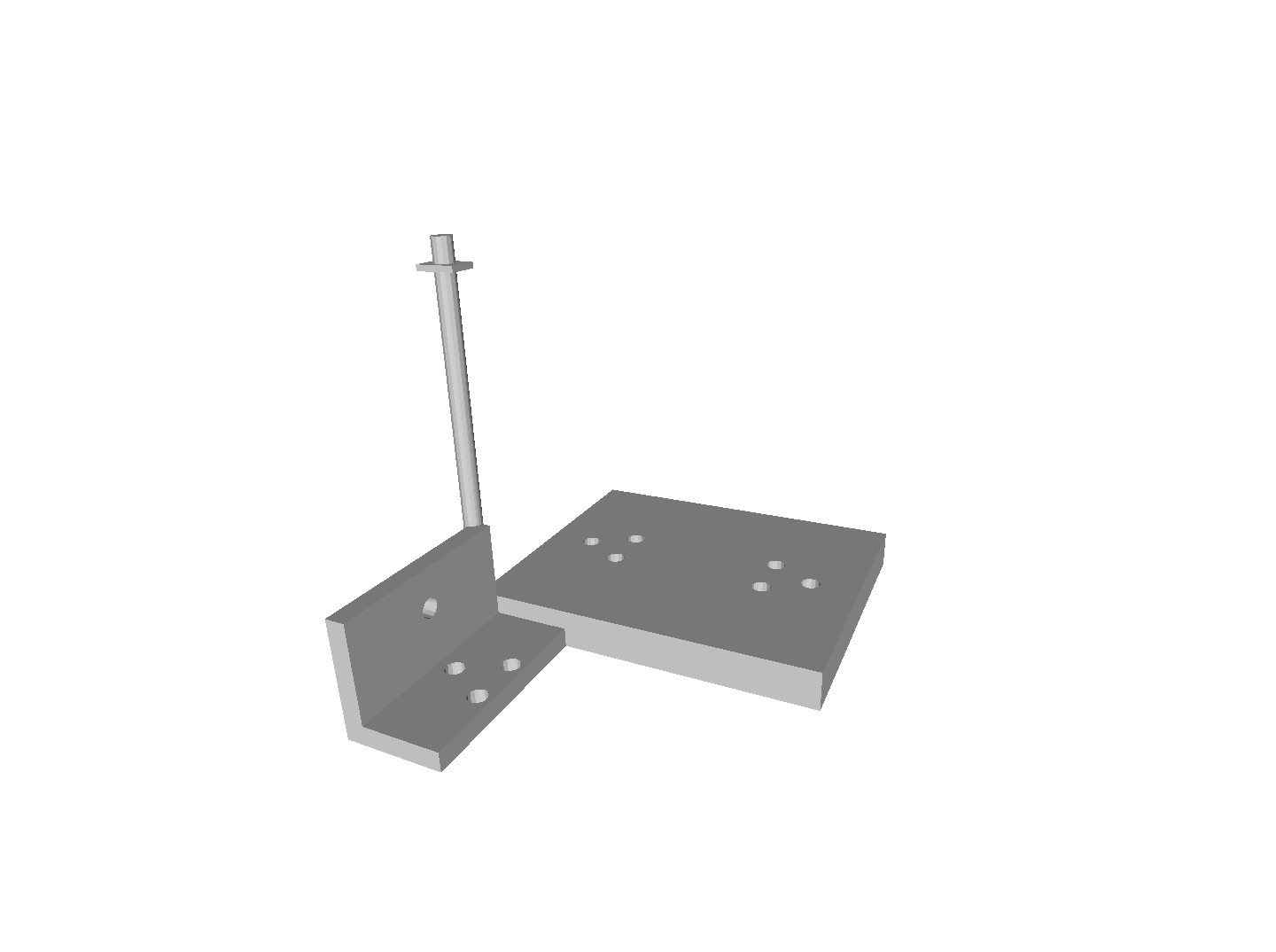
}However, if I open the meshes in Meshlab, the parts are not placed correctly, see the enclosed printscreen. As far as I understand, in the STEP file the parts are created in some initial position and then copied to various places. How do I move them to where they should be? Certainly I am missing something very basic. Many thanks!
Attachments:
Tue, 07/11/2017 - 20:17
Hi Dominik,
you could get the locations from XCAFDoc_ShapeTool:
myAssembly->GetLocation(theLabel);
and multiply the Shape with the location.
Greets,
Patrik
Tue, 07/11/2017 - 20:37
Dear Patrik,
thank you very much. I have tried this already before asking and, unfortunately, it had not really worked out.
Updated code:
The positions change, but not really the way I would like them to, see the new printscreen.
I have even tried inverting the transformation with transformation.Invert(), without success.
Thanks for hints!
Tue, 07/11/2017 - 21:05
Hi Dominik,
don't forget the checking for references, they also can have transformations!
Standard_Boolean isRef = myAssembly->GetReferredShape(theLabel, refLabel);
Greets,
Patrik
Wed, 07/12/2017 - 11:38
Hi Peter,
thanks, I did not think of this! Do I just multiply the transformations then or is there something more elaborate to do?
When I multiply them like this:
they are still not correctly positioned (printscreen attached). I have also tried changing the order of the transformations and --- somewhat surprisingly --- the result looks the same (shouldn't they be non-commutative?).
Thanks for suggestions!
Wed, 07/12/2017 - 19:51
Hmm,
I also solve assemblies using their transformations, to get the whole structure.
But another idea:
your sample file is the same as in the XDE documentation. You have references and referenced assemblies (see the XDE screenshots)
would modify the transformation for the original (referenced) shape.
Have you tried to copy the shape inside:
?
Greets,
Patrik
Thu, 07/20/2017 - 11:49
Dear Patrik,
thank you for your hint and sorry for my late reply.
I tried adding the "Standard_True" parameter to BRepBuilderAPI_Transform as you had suggested.
I did so both in my code from 11 July, 2017 19:37 and the code from 12 July, 2017 - 10:38.
Unfortunately, it does not change anything in either of the situations.
I've had a closer look at the transformations and there is a thing I do not understand.
The shapes corresponding to i=6 and i=9 both represent the same geometrical shape and they both have the same transformation, represented by the matrix
-1 0 0 2.5
0 1 0 -17.5
0 0 -1 -20
0 0 0 1
Consequently, they both end up in the same location, which is not what I want.
Multiplication by the transformation of the referred shape does not change anything about it.
I feel I am missing something rather basic ...
Thanks for further suggestions.
Thu, 07/20/2017 - 12:44
Hi Dominik,
I still don't see assemblies usage in your code.
Something like this:
if (isAssembly)
{
TDF_LabelSequence shapeLabels;
pShapeTool->GetComponents(realLabel, shapeLabels, Standard_False);
Standard_Integer nbShapes = shapeLabels.Length();
for (Standard_Integer i = 1; i <= nbShapes; i++)
{
const TDF_Label& childLabel = shapeLabels.Value(i);
if (m_xdeUtils.GetShapeTool()->IsFree(childLabel))
{
theMat = GetMaterial(childLabel);
ReadShape(childLabel, tmpResult, theMat);
}
}
if (tmpResult->NbChildren() > 0)
result = tmpResult;
}
ReadShape is my method (recursive call from assemblies). You can store the transformations to a stack or something to calculate the absolute transformation. An assembly can have a transformation and the children too (and also be referenced)...
See the screenshot for the whole model structure...
Greets,
Patrik
Mon, 07/24/2017 - 17:52
Hi Patrik,
I#m also interested in loading step files and exploring the xcaf datastructure, especially for material information. What exactly do you mean by store the transformations to a stack? Is the variable tmpResult in your example the TopoDS_Location of the current Shape? Where to you calculate and apply the transformation for each shape?
Thnank you in advance!
Best regards
Tue, 07/25/2017 - 11:54
Hi David,
tmpResult is an instance of my node class. Dominik wants to have absolute shapes, so he has to calculate these matrices. He can build a matrix stack for calculating the absolute matrix for each shape. It really depends on his implementation.
I use for myself a kind of scene graph and can reuse the relative matrices. I need the absolute matrices for example when doing an OBJ output.
Best regards,
Patrik