

Mon, 08/26/2019 - 13:50
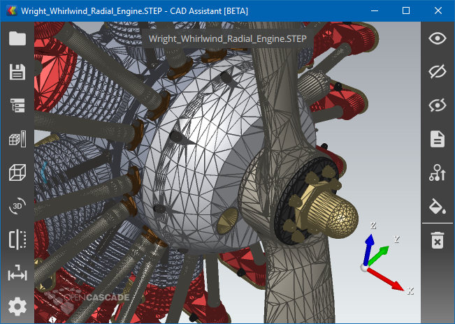
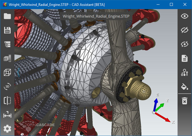
Mesh displayed in 3D Viewer may come from different sources - imported from external file (glTF, JT, STL, PLY, OBJ), computed for analytical BRep geometry by BRepMesh (part of OCCT) and ExpressMesh (OCC component) algorithms or generated directly by application code.
The mesh is usually displayed shaded, but such a presentation is not suitable for analysis of mesh structure. In many cases, application developer needs other mesh presentations to locate issues (too many details, not enough details, local deviations, etc.) and make corrections based on analysis results (adjust mesh generation or export parameters).
In this case, mesh edges presentation becomes very helpful.

Draw Harness test case for Mesh Edges (Geometry Shader).
Historically, OCCT provides Shaded [AIS_Shaded] and Wireframe [AIS_WireFrame] display modes for BRep shapes (AIS_Shape), but the latter one should not be confused with mesh edges presentation (mesh wireframe, as called in some other visualization applications). AIS_WireFrame consists of face boundaries, surface isolines, free edges, and has nothing in common with mesh edges presentation (apart from displaying thin edges).
But actually, OCCT provided a way for displaying mesh edges for AIS_Shaded presentation - through glPolygonMode(GL_LINES) feature provided by OpenGL library, accessible via Graphic3d_AspectFillArea3d properties. Polygon Mode feature is, however, not provided with OpenGL ES (mobile) API, and also has limitations on desktop OpenGL implementations. Forthcoming OCCT 7.4.0 release introduces improved Draw Edges option using Geometry Shader available on modern graphic hardware, including mobile one (OpenGL 3.2+ and OpenGL ES 3.2+)..
Alternative Approaches
Three mesh edges presentations have been compared:
- Polygon Mode for array of triangles (glPolygonMode).
- Dedicated lines array.
- Geometry Shader program for array of triangles (new).
Each solution has its cons and pros, summarized below:
1. glPolygonMode.
CONS:
- Unavailable on OpenGL ES.
- Rendering interior + mesh edges requires 2 passes.
- Hardware has to render edges shared between triangle twice, reducing performance.
- Wide lines are rendered with visual artifacts.
- Fixed line width (1 pixel) on OpenGL, Core Profile.
- Triangles only.
PROS:
- Easy to switch on.
- Line width in pixels.
2. Dedicated lines array.
CONS:
- Extra memory footprint for additional data.
- Presentation data should be recomputed.
- The same limitations with line width as glPolygonMode
(1 pixel width with Core Profile, visual artifacts on wide lines).
PROS:
- Better performance than glPolygonMode(),
because duplicated triangle edges can be filtered in advance so that only unique ones tol be drawn. - Can be computed for arbitrary polygons (triangles/quads/polygons).
3. Geometry Shader program.
CONS:
- Requires Geometry Shader stage,
which is unavailable on old graphic hardware or can be slow on old hardware. - Variable line width,
becoming twice thicker on edges shared between triangles. - Visually hollow presentation without AntiAliasing
might look not as good as normal lines array.
PROS:
- Arbitrary line width,
no limitation within Core Profile,
no artifacts on wide lines. - Variable line width,
becoming thinner at large camera distance;
this avoids mesh becoming a solid mess at distance. - Rendering interior + mesh edges presentation within single pass.
- Shrinking element presentation (as transparent mesh edges).
- Triangles and quads edges;
quads should be split into triangles in specific edges order. - Switching on the fly without recomputing presentation,
as in case of glPolygonMode. - Smooth mesh edges on top of interior without AntiAliasing.
The 3rd approach provides a good compromise between performance, functionality and simplicity to activate. Since mesh edges presentation is usually auxiliary one, used for application development or for mesh analysis, the ability to activate this presentation for already computed triangulation arrays without recomputation is very important. The second approach remains available, but is expected to be implemented at application level, when needed. Geometry Shader is now used by default, while first (glPolygonMode) can be enabled via OpenGl_Caps::usePolygonMode option.
Visual Comparison
Three approaches demonstrate different visual features at different scenarios.
Edges drawn using dedicated Lines array.
Edges drawn using glPolygonMode().
Edges drawn using Geometry Shader.
As can be seen on screenshots above, mesh edges drawn as lines (dedicated Lines array or glPolygonMode()) behave differently comparing to new Geometry Shader. Geometry Shader defines threshold making lines thinner for too small triangles, so that geometry details and interior color remain distinguishable.
Edges on Quad-dominant mesh (Geometry Shader).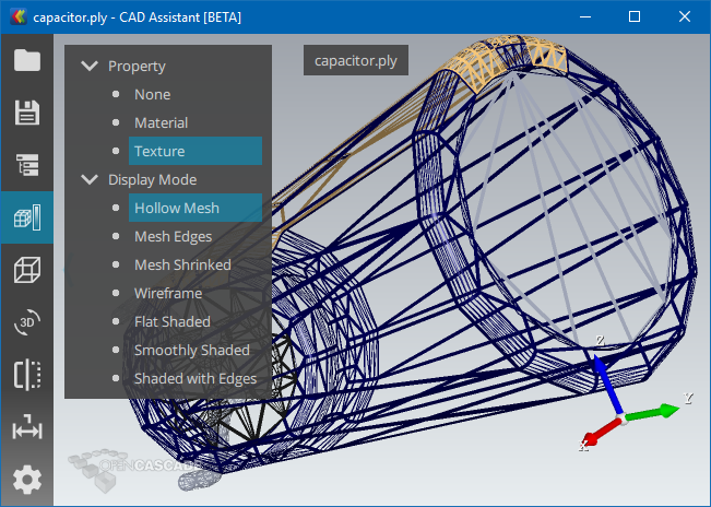
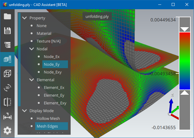
Hollow Mesh presentation (Geometry Shader).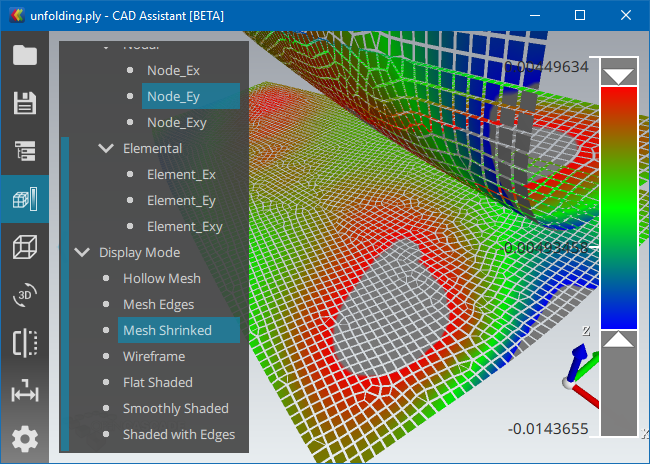
Shrunk Mesh presentation (Geometry Shader).
Geometry Shader also allows implementing another nice looking presentation of mesh - Shrunk Mesh presentation. All these modes (Hollow Mesh, Mesh Edges, Mesh Shkinked, Smoothly Shaded, Flat Shaded) can be now switched on the fly within Open CASCADE CAD Assistant version 1.3.
Performance Comparison
The following charts provide a comparison of the performance of the new display mode for mesh edges (green bar) against two other display modes described above, with baseline being performance of display of shaded triangulation without mesh edges (blue bar). The performance is measured in FPS (frames per second).
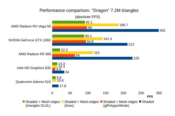
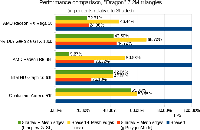
The first test has been done using “Dragon” model, which is a PLY file defining 7.2M triangles and no assembly structure. This is a good test for a raw rendering performance of different approaches.
As can bee seen on comparison charts, unique Mesh Edges collected in advance and drawn using GL_LINES primitives on top of triangulation demonstrates the best performance results, but requires extra geometry data. Radeon hardware reacts badly on presence of Geometry Shader, so that on Radeon R9 380 using glPolygonMode is faster than extra Geometry Shader, while GeForce GTX 1060 and Radeon RX Vega demonstrate performance similar to glPolygonMode. At the same time, Intel HD Graphics 630 and Qualcomm Adreno 510 demonstrate performance close to dedicated lines array when using Geometry Shader.

The second test has been done only on Qualcomm Adreno 510, on the various models. It shows that, depending on model structure, Geometry Shader approach might be even faster than dedicated geometry drawing lines.
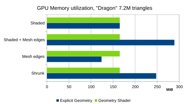
Another chart shows graphics memory required for drawing various presentations with GLSL Geometry Shader (the same triangulation is used for all presentations) and explicitly generated Geometry.
Usage
More details on implementation of the new feature can be found in Mantis issue #0029076 “Visualization - implement element shrinking Shader”. Mesh edges are controlled via Graphic3d_AspectFillArea3d::SetDrawEdges(), ::SetEdgeColor(), ::SetEdgeWidth() properties.
Check documentation of vaspects command for playing with mesh edges and interior styles in Draw Harness. Here is a sample script:
pload MODELING VISUALIZATION
psphere s 1
box b 2 0 0 1 2 3
vinit
vdisplay -dispMode 1 s b
vfit
vaspects b -interior EMPTY -drawEdges 1 -edgesColor RED
vaspects s -interior SOLID -drawEdges 1 -edgesColor BLACK