

Tue, 07/25/2017 - 10:50
Hi Everyone,
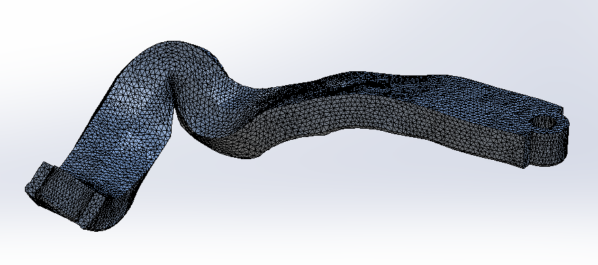
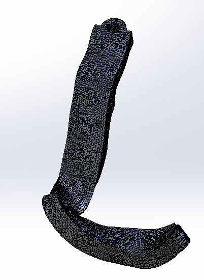
I have an STL file of a plate(Orthopedic plate) which is used in fixation of bones. I am working on the topic of generating an algorithm for a machine capable of bending this type of plate. The STL file has been generated via CT scanning. In this plate, it has features like Bending in two directions, twisting, and holes. In the algorithm, I must find the exact position of the bends and holes so that command can be given to machine to do the bending and twisting sequentially. Since I have not used OpenCascade earlier so I'm not sure whether this kind of problem can be solved using this tool. I, actually, have no idea how to straightforwardly proceed with this topic. I have started this topic by feature recognition method.
Any help will be appreciated.
Thank you for giving your time in reading this.
Cheers,
Aman Kumar
Tue, 07/25/2017 - 11:18
Hello Aman,
OpenCascade is precise B-Rep modeling kernel. Your data is a faceted 3D. There is no API in OpenCascade which is helpful in your case. You may try to reverse engineer your model using commercial software like Geomagic or SpaceClaim. After that some curvature analysis can be applied to the resulting NURBS to find non-planar zones where bends could exist. Or, if you find a way to reverse engineer it smartly, you may even end up with individual faces representing your holes and bends. Still, there is a big deal of custom development in your problem. It requires additional research. Some preliminary questions are:
- Do you need a fully automatic solution, or user interaction is allowed?
- Can you precise the term "bend" for the given models? Which series of triangles would you call "bends" there?
Tue, 07/25/2017 - 12:01
Thank you so much for your prompt reply.
1) Yes, I'm seeking a fully automatic solution as the machine is capable of both- bending and twisting of the plate.
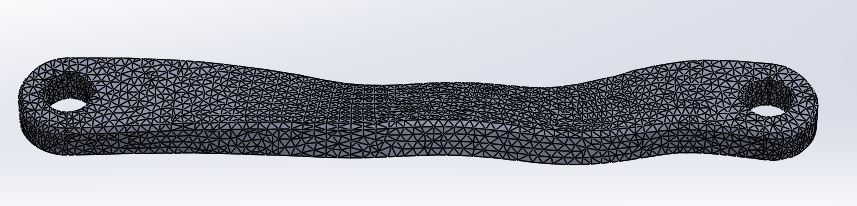
2) I have attached Plate4 named files to show what the term bend is. The pic named Plate1 has too much bent so almost at every point we can see some irregular free form surface (which has been made by forced bending).
Tue, 07/25/2017 - 12:27
In sheet metal forming (your Plate4.jpg), a bend feature is unambiguously defined as simply a pair of cylindrical surfaces. In your case, it seems like a bend was altered by twist, etc. As a result, your STL models look like the result of some generalized warping which will be very tricky to trace back a series of bends. You say that you are looking at feature recognition now. I believe, this is a correct way. Though, it is likely that you need to reconstruct a precise B-Rep from STL before you can recognize any meaningful features. And, after all, it will be extremely difficult to find bends in a highly warped model.
Tue, 07/25/2017 - 13:09
I had a feeling that this twist is going to give me a lot of pain, so I am making this complex problem into easier one by working on bending only. As given in Plate4.jpg file, I have made a similar CAD of a simple bent plate at 120degree (shown in image.png) and now I am trying to find the angle using python code. I have used numpy-stl to import the stl file in python but I am not able to find the angles between the two planes. (At first, I'm trying with one bend, then I'll make many more to find all relative angles) I don't know how to identify the cylindrical surface as it is tangent to both the planes (which are making an angle of 120degree). How should I start? Can I have your email ID?
Tue, 07/25/2017 - 15:06
Since you are fighting with STL, there is no cylindrical surface. Cannot you use precise CAD instead? If not, I suggest you to reverse engineer your model first. Check paper by T. Varady to get started: "Varady, T., Martin, R.R., and Cox, J. 1997. Reverse engineering of geometric models - An introduction. Computer-Aided Design 29, 255–268."
Wed, 07/26/2017 - 08:54
I do have the cad file of the (image.png) file (which is bent at 120degrees). How to proceed in that case? Do we have to recognize feature using BRep or some other method?
Do you have any research paper link/name related to this?
Wed, 07/26/2017 - 10:36
There are many. Actually, if you have a CAD file, this recognition will be much simpler. A good survey on the subject is "Han, J.H.J., Pratt, M., and Regli, W.C. 2000. Manufacturing feature recognition from solid models: a status report. IEEE Transactions on Robotics and Automation 16, 6, 1–31." I will recommend recognition based on face adjacency graphs. In the fundamental textbook "Shah, J.J. and Mantyla, M. 1995. Parametric and Feature Based CAD/CAM: Concepts, Techniques, and Applications. John Wiley & Sons, Inc., New York, NY, USA." this is called "procedural recognition" (page 337). Also you may want to ask for support from OPEN CASCADE to benefit from our feature recognition solutions.
Wed, 07/26/2017 - 11:07
I just realized that the aim of the project is to make the problem simple and not to do to much laborious work by converting STL file to solid model using reverse engineering and then doing the process. Suppose if somehow I am able to achieve that, it won't be user-friendly. Every time I scan a new plate, I'll have to manually do the reverse engineering process and then do feature recognition which will eliminate the requirement of "automation" as the process should involve taking scanned file and feeding the data to the machine.
Can you suggest some process that uses stl file to do the processing ?
I found this paper: http://www.sciencedirect.com/science/article/pii/S0010448508000195 which I think is in accord with my requirement. What do you think?
Wed, 07/26/2017 - 13:29
Aman, the paper by V. Sunil looks promising. As mentioned by authors, STL is essentially a "bucket of faces" with no topological information available to recognizer. Therefore, to proceed with feature identification, a doze of reverse engineering is still required. In this case, they reverse engineer regions by segmentation. For that, they need to evaluate discrete curvatures and guess the underlying surface types. To some extent, this can be done automatically, but... You should take such declarations with a grain of salt, since mesh models essentially lose the original design intent and recovering it fully automatically is still a challenge. You may also want to check "Gao, S., Zhao, W., Lin, H., Yang, F., and Chen, X. 2010. Feature suppression based CAD mesh model simplification. CAD Computer Aided Design 42, 12, 1178–1188.". They use some variation of watershed segmentation algorithm prior to feature recognition.