

Wed, 02/09/2022 - 15:30
Hello,
I'm working on a viewer using OpenCASCADE. The user uses the STEP format to load geometric shapes. Actually, everything is working fine so far.
First of all, these geometric shapes go into a kind of simulation and draw conclusions according to calculation. I have thousands of rows of data output consisting of 4 columns of X, Y, Z, and Value. These data show the interaction values of a point in 3D space.
My problem starts here. I want to colorize 3D shapes according to these results. I've tried two different methods so far. I don't know which is the correct method. I would like to get your ideas for more suitable solutions.
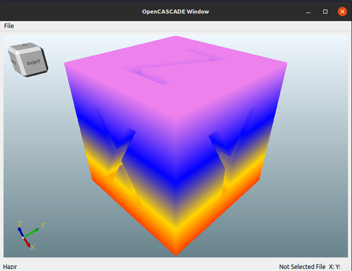
The first method is can make a color map on Meshed surfaces by reading STL. The downside to this is that I have to convert the geometries to Mesh surfaces every time. It will be much faster for me to work on AIS_Shape read directly from the STEP file. (first-method-stl-color-mapping.png)
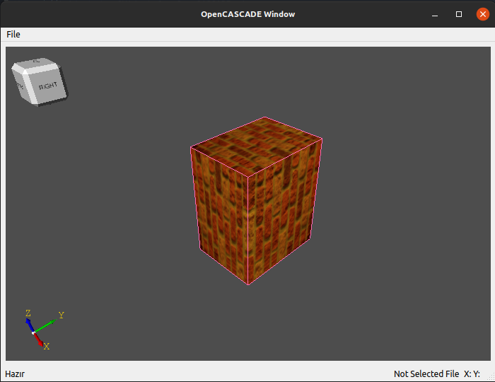
The second method is I read the AIS_Shapes from the STEP file. I can add texture to the surfaces from png format. In this, I need to process the data and create a texture file in PNG format. This can take quite a long time. (second-method-ais-object-textured.png)
Is there a much more convenient way to visualize the assembly file read from STEP format as I have attached in the sample picture (sample.jpg)?
Thanks, Hakan.
Wed, 02/09/2022 - 22:43
What is displayed on the sample.jpg looks like a colormapping of some FEA algorithm - which usually computes results for mesh elements, not for shapes. So that there is no problem for solving "how to color a shape" here - you first prepare a mesh for analysis, then put it solver (it might require mesh to have a specific properties, so that a visualization mesh might not work well), and solver provides computation results mapped onto mesh elements / nodes.
If I read this correctly:
then I may guess that you have a plenty of data appeared in 3D space and not mapped onto shape or mesh. E.g. you are trying to map some arbitrary collected data from real sensor onto design shape. This mapping might involve expensive computations - first you need to generate a mesh with desired quality, then you may try to map each 3D point onto the closest mesh element and either generate some texture or to generate mesh of extra density so that values would map nicely.
If point data is very dense - then you may display a colored Point Cloud on top of a shape or to reconstruct a surface from this Point Cloud.
AIS_Shape doesn't display shapes - it performs tessellation of B-Rep using BRepMesh tool and displays result triangulation. So I don't really see how it is different from STL here (apart from STL is a very bad file format for storing triangulation).
Thu, 02/10/2022 - 14:10
Hi Kirill,
Thank you for the answer. This looks like it's going to be a lot harder work than I thought. As a result of my research, I have seen a lot of FEA studies in the python vtk field. Is there an open source sample application for OpenCASCADE?