

Sun, 02/20/2022 - 18:58
Forums:
Hi,
after assembling a work setup I started to workout face selection.
I rotate all elements to desired position and on selecting a face, I calculate a plane from the face and calculate intersection with the blue transparent box.
Blue box is a Handle(AIS_Shape) member variable and rotation is performed like this:
void OcctQtViewer::rotate(double dA, double dB, double dC) {
  qDebug() << "OcctQtViewer::rotate(" << dA << "/" << dB << "/" << dC << ")";
  gp_Quaternion q;
  gp_Trsf       r;

  q.SetEulerAngles(gp_Intrinsic_XYZ, dA, dB, dC);
  r.SetRotation(q);
  TopLoc_Location       tll(r);
  AIS_ListOfInteractive shapes;

  myContext->DisplayedObjects(shapes);
  for (Handle(AIS_InteractiveObject)& s : shapes) {
      qDebug() << s->get_type_name();
      if (s->DynamicType() == STANDARD_TYPE(AIS_ViewCube)) continue;
      myContext->SetLocation(s, tll);
      }
  myView->Invalidate();
  update();
  }
The horizontal rectangle in red is the result of intersection (BRepAlgoAPI_Section), but it does not take the actual rotation of the blue box into account. Instead the intersection shows the unrotated blue box.
How can I get rid of visible location of blue box? Rotation seems to work for selected faces, but not for unselectable parts.
Attachments:
Mon, 02/21/2022 - 19:29
Hi,
I'm sorry if my question is too dumb. I spent nearly all my sparetime reading occ docs - and occ is huge!
I read, that presentation creates internal graphic structures from AIS_Shape. I have lots of faces and edges displayed by interactive context, but I need only one shape for boolean operations with selected faces.
As written, selected faces are always "right" oriented. Only the shape of interest looses connection to shape displayed by context.
Is there a way to get current shape back from internal graphic structures of presentation?
Or what is best way to get rid of changes made by context?
Tue, 02/22/2022 - 11:49
I guess it is difficult to help because it is difficult to understand the problem (at least to me).
Tue, 02/22/2022 - 18:55
Hi Sir,
thank you very much for your attention.
May be I did something I should not ...
I'll try to explain the whole workflow together with my plans:
I start by loading a cad-model. Currently cad model may be brep or step.
That leads to a single shape, which I display in occ-viewer (SC_Setup01.jpg)
That model may be rotated and moved to your will.
On pressing "Set" button, rotation and move will be included into shape, so that reset-location won't change aspect of model.
Second step starts with increased bounding box (SC_Setup02.jpg). I fill spinboxes with values from bounding box, so the user may change size and position of blue box (the raw workpiece). On pressing "Set" size and location will be used to create a new shape.
Step three is creation and modification of clamping plug (SC_Setup03.jpg)
Step four is selection and moving of vise (SC_Setup04.jpg). Complete model shape is not displayed any more.
Finishing step four - and whole setup - with "Set" will fix vise and create an exploded model (faces and edges become selectable) (SC_Setup05.jpg).
Notebook is then switched to "Info" tab. Upper listbox shows the edges of possibly selected face, lower listbox will show detail information for selected edges from upper listbox.
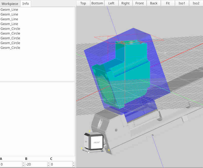
Idea is now to rotate whole setup, so that normal of selected face becomes vertically oriented (not implemented yet). Actually I'm rotating setup with the spinboxes (A, B, C).
In picture SC_Work01.jpg I selected the top most face.
In selection handler I create an offset plane, if selection is a plane face.
From that offset shape I create a surface and then I calculate intersection of that surface with the blue box (well, that's what I want to do, not what really happens).
The result of intersection is displayed using red color (the red rectangle).
Its obvious, that size and location of the red rectangle is not what I'd expected. Therefore I thought, may be interactive object displayed by context is different to the interactive object, I have a handle from as member var.
I tried to get current location from context, but applying that to the shape, I have the handle from does not lead to expected result.
Now my question is, what am I doing wrong or how can I access the blue box in the state, displayed in viewer. So that calculation of intersection will draw lines on the faces from blue box.
Rotation of whole setup happens by qt-connections, actual class is not involved.
Hope I could explain my problem.
Fri, 02/25/2022 - 15:41
Hello,
I don't get it. What ever I tried, nothing works for me.
Could someone please gimme a hand on how to get the four verices of the surrounding box for any selected face of the model?
The model is completely inside the blue box, so the selected face needs to get extended so that it cuts the box. That cutting plane creates 4 corners that belong to the box and the plane.
What is the right way to go for that?